1900 Work Wirelsess Telegarphy
Recognised text
Text below was produced by optical character recognition and may contain errors. Check it against the original.
98

WORK.

(No. 597—August 95, 1909,

WIRELESS TELEGRAPHY STATIONS,
BY DR. THOMAS AGIUS.

Most of the apparatus required at a wireless telegraphy
station is within the means of the mechanical amateur.
The induction coil should give a spark at least 1 in. long,
and the greater the length, other things being equal,
the greater may be the distance between the stations.
If the spark measures much less than 1 in., delicate
instruments are required at the receiving station. The
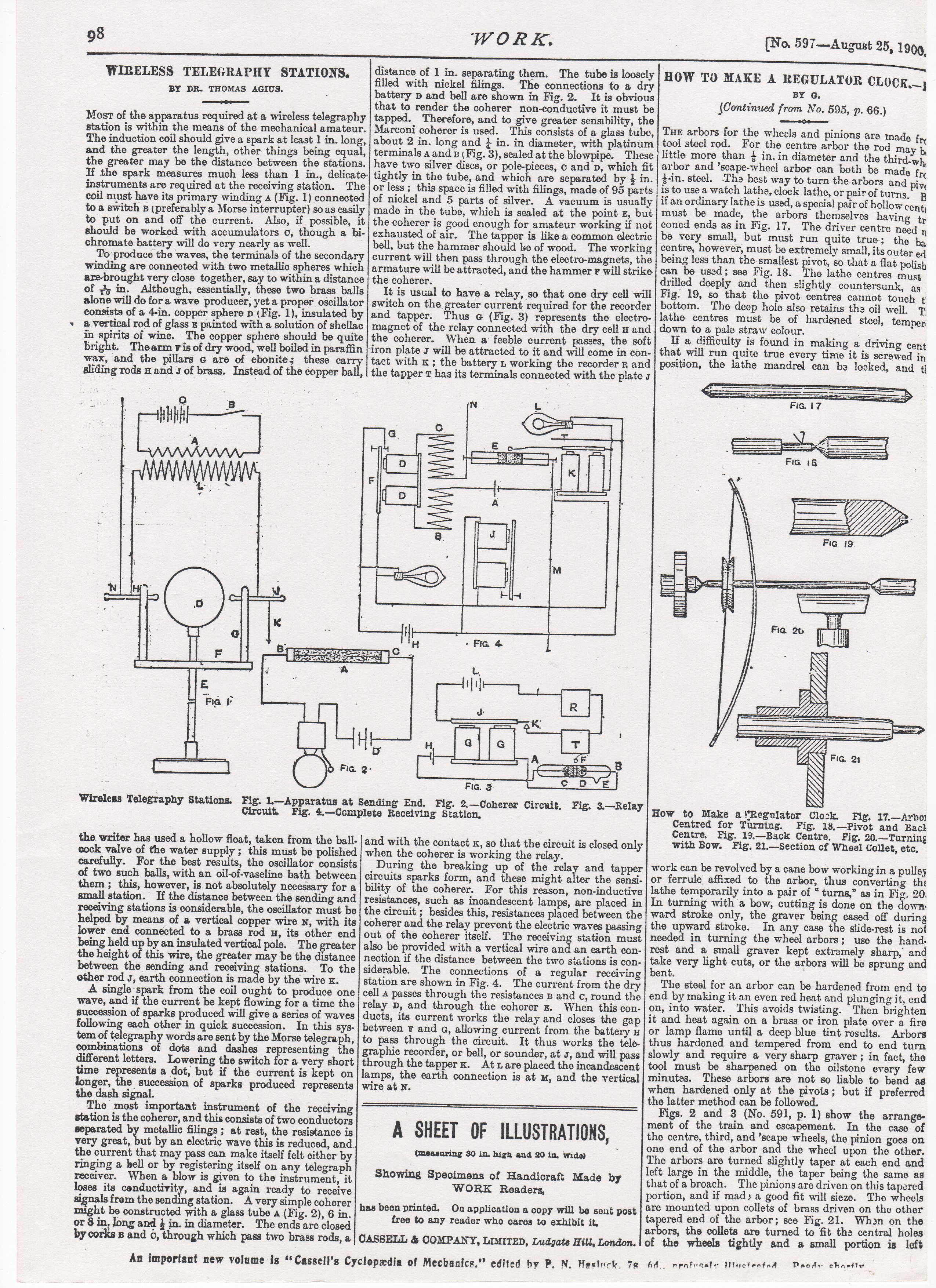
coil must have its primary winding a (Fig. 1) connected
to a switch g (preferably a Morse interrupter) so as easily
to put on and off the current. Also, if possible, it
should be worked with accumulators o, though a bi-

chromate battery will do very nearly as well.

To produce the waves, the terminals of the secondary
winding are connected with two metallic spheres which
are-brought very close together, say to within a distance
of ¥, in. Although, essentially, these two brass balls
alone will do fora wave producer, yet a proper oscillator
consists of a 4-in. copper sphere p (Fig. 1), insulated by
a.vertical rod of glass painted with a solution of shellac
The copper sphere should be quite
t. Thearm vis of dry wood, well boiled in paraffin
wax, and the pillars G are of ebonite; these carry
sliding rods u and s of brass. Instead of the copper ball,

in are of wine.
brig

distance of 1 in. separating them. The tube is loosely
filled with nickel filmgs. The connections to a d:
battery p and bell are shown in Fig. 2. _ It is obvious
that to render the coherer non-conductive it must be
tapped. Therefore, and to give greater sensibility, the
Marconi coherer is used. This consists of a glass tube,
about 2 in. long and 4 in. in diameter, with platinum
terminals 4 and B (Fig. 3), sealed at the blowpipe. These
have two silver discs, or pole-pieces, c and p, which fit
tightly in the tube, and which are separated by } in.
or less ; this space is filled with filings, made of 95 parts
of nickel and 5 parts of silver. A vacuum is usually
made in the tube, which is sealed at the point z, but
the coherer is good enough for amateur working if not
exhausted of air. The tapper is like a common electric
bell, but the hammer should be of wood. The working
current will then pass through the electro-magnets, the
armature will be attracted, and the hammer F will strike.
the coherer. 2

It is usual to have a relay, so that one dry cell will
switch on the greater current required for the recorder
and tapper. Thus @ (Fig. 3) represents the electro-
magnet of the relay connected with the dry cell # and
the coherer. When a@ feeble current passes, the soft
‘iron plate s will be attracted to it and will come in con-
tact with x ; the battery L working the recorder R and
the tapper T has its terminals connected with the plate s

Wireless Telegraphy Stations. Fig. L—Apparatus at Sending End. Fig. 2.
Circuit. Fig. 4.—Complete Receiving Station.

the writer has used a hollow float, taken from the ball-
cock valve of the water supply ; this must be polished
carefully. For the best results, the oscillator consists
of two such balls, with an oil-of-vaseline bath between
them ; this, however, is not absolutely necessary for a
small station. If the distance between the sending and
receiving stations is considerable, the oscillator must be
helped by means of a vertical copper wire x, with its
lower end connected to a brass rod Hu, its other end
being held up by an insulated vertical pole. The greater
the height of this wire, the greater may be the distance
between the sending and receiving stations. To the
other rod 5, earth connection is made by the wire x.

A single ‘spark from the coil ought to produce one
wave, and if the current be kept flowing for a time the
succession of sparks produced will give a series of waves
following each other in quick succession. In this sys-
tem of telegraphy words are sent by the Morse telegraph,
combinations of dots and dashes representing the
different letters. Lowering the switch for a very short
time represents a dot, but if the current is kept on
longer, the succession of sparks produced represents
the dash signal.

The most important instrument of the receiving
station is the coherer, and this consists of two conductors
separated by metallic filings; at rest, the resistance is
very great, but by an electric wave this is reduced, and.
the current that may pass can make itself felt either by
ringing a hell or by registering itself on any telegraph
receiver. When a blow is given to the instrument, it
loses its conductivity, and is again ready to receive
signals from the sending station. A very simple coherer
might be constructed with a glass tube a (Fig. 2), 6 in.
or 8 in, Jong and } in. in diameter. The ends are closed
by corks 5 and 6, through which pass two brass rods, a

An important new volume is “‘Cassell’s Cyclopedia of Mechanics,” edited by P. N. Heslick. 78 64.. nrnfraale iucteotad

| oa ae : =
ing | JB ie
| W, alee
ea [
8

ie «
it]
J eo |
K
3 d
qelle] z
fe A F P
Be: ral

—Coherer Circuit, Fig. 3.—Relay

Fic. ¢-

and with the contact x, so that the circuit is closed only
when the coherer is working the relay.

During the breaking up of the relay and tapper
circuits sparks form, and these might alter the sensi-
bility of the coherer. For this reason, non-inductive
resistances, such as incandescent lamps, are placed in
the circuit ; besides this, resistances placed between the
coherer and the relay prevent the electric waves passing
out of the coherer itself. The receiving station must
also be provided with a vertical wire and an earth con-
nection if the distance between the two stations is con-
siderable. The connections of a regular receiving
station are shown in Fig. 4. The current from the dry
cell a passes through the resistances B and c, round the
relay D, and through the coherer x. When this con-
duets, its current works the relay and closes the gap
between ¥F and «, allowing current from the battery u
to pass through the circuit. It thus works the tele-
graphic recorder, or bell, or sounder, at J, and will pass
through the tapperx. At1are placed the incandescent
lamps, the earth connection is at m, and the vertical
wire at N.

A SHEET OF ILLUSTRATIONS, |

(measuring SO in. high and 20 in. wide)

Showing Specimens of Handicraft Made by
WORE Readers,

has been printed. On applicationa copy will be sent post
free to any reader who cares to exhibit it,

SS ani
HOW TO MAKE A REGULATOR CLOCK;
BY G.
{Continued from No. 595, p. 66.)
te
Tur arbors for the wheels and pinions are made fre
tool steel rod. For the centre arbor the rod ma
little more than i in. in diameter and the third-wh,
arbor and ’scape-wheel arbor can both be made

: f
}-in. stecl. Tha best way to turn the arbors and oe
is to use a watch lathe, clock lathe, or pair of turns. R

ifan ordinary lathe is used, a special pair of hollow co:
must be made, the arbors themselves having
coned ends asin Fig. 17. The driver centre need y
be very small, but must run quite true; the ba
centre, however, must be extremely small, its outer eq
being less than the smallest pivot, so that a flat polish
can be used; see Fig. 18. The lathe centres Must
drilled deeply and then slightly countersunk, as
Fig. 19, so that the pivot centres cannot touch t!
bottom. The deep hole also retains the oil well. Ty
lathe centres must be of hardened steel, temper
down to a pale straw colour.

If a difficulty is found in making a driving cent
that will run quite true every time it is screwed in
position, the lathe mandrel can ba locked, and ¢j

How to Make a'Regulator Clock. Fig. 17.—Arboi
Centred for Turning. Fig. 18,—Pivot and Bact
Centre. Fig. 19.—Back Centre, Fig. 20.—Turning
with Bow. Fig. 21.—Section of Wheel Collet, etc,

work can be revolved by a cane bow working in a pulley
or ferrule affixed to the arbor, thus converting the
lathe temporarily into a pair of “ turns,” as in Fie. 20,
In turning with a bow, cutting is done on the down:
ward stroke only, the graver being eased off during
the upward stroke. In any case the slide-rest is not
needed in turning the wheel arbors; use the hand.
rest and a small graver kept extremely sharp, and
take very light cuts, or the arbors will be sprung and
bent. :

The steel for an arbor can be hardened from end to
end by making it an even red heat and plun ging it, end
on, into water. This avoids twisting. Then brighten
it and heat again on a brass or iron plate over a fire
or lamp flame until a deep blue tint rosults. Arbors
thus hardened and tempered from end to end turn
slowly and require a very sharp graver ; in fact, the
tool must be sharpened on the oilstone every few
minutes. These arbors are not so liable to bend ag
when hardened only at the pivots; but if preferred
the latter mothod can be followed.

Figs. 2 and 3 (No. 591, p. 1) show the arrange-
ment of the train and escapement. In the caso of
the centre, third, and ’scape wheels, the pinion goes on
one end of the arbor and the wheel upon the other.
The arbors are turned slightly taper at each end and
left large in the middle, the taper being the same as
that ofa broach. The pinions are driven on this tapered
portion, and if mad» a good fit will sieze. Tho wheels
are mounted upon collets of brass driven on the other
tapered end of the arbor; sce Fig. 21. When on the
ace the collets are turned to fit tha central holes

OASSELL & COMPANY, LIMITED, Ludgate Hill, London.

of the wheels tightly and a small portion is left

Prody chaetty —