Alford1
Recognised text
Text below was produced by optical character recognition and may contain errors. Check it against the original.
68 Proceedings of the I.R.E.

the voltage of the virtual generators is not e=j2sI, but
¢' =j2s sin Ts and the radial field of the line is now
inducing not only a virtual generator in the short-
circuiting bar of the section but also one in each of the
two vertical wires at the bend in the section. The volt-
age of each of these two additional generators is
e=sV, or exactly half of that of the virtual generator
in the short-circuiting bar; voltage V, which appears
in the expressions for these generators is, of course, the

Zo KK
— st v, LINES or

A
-, CY LINE 2 Vp
A

e

___*Z,

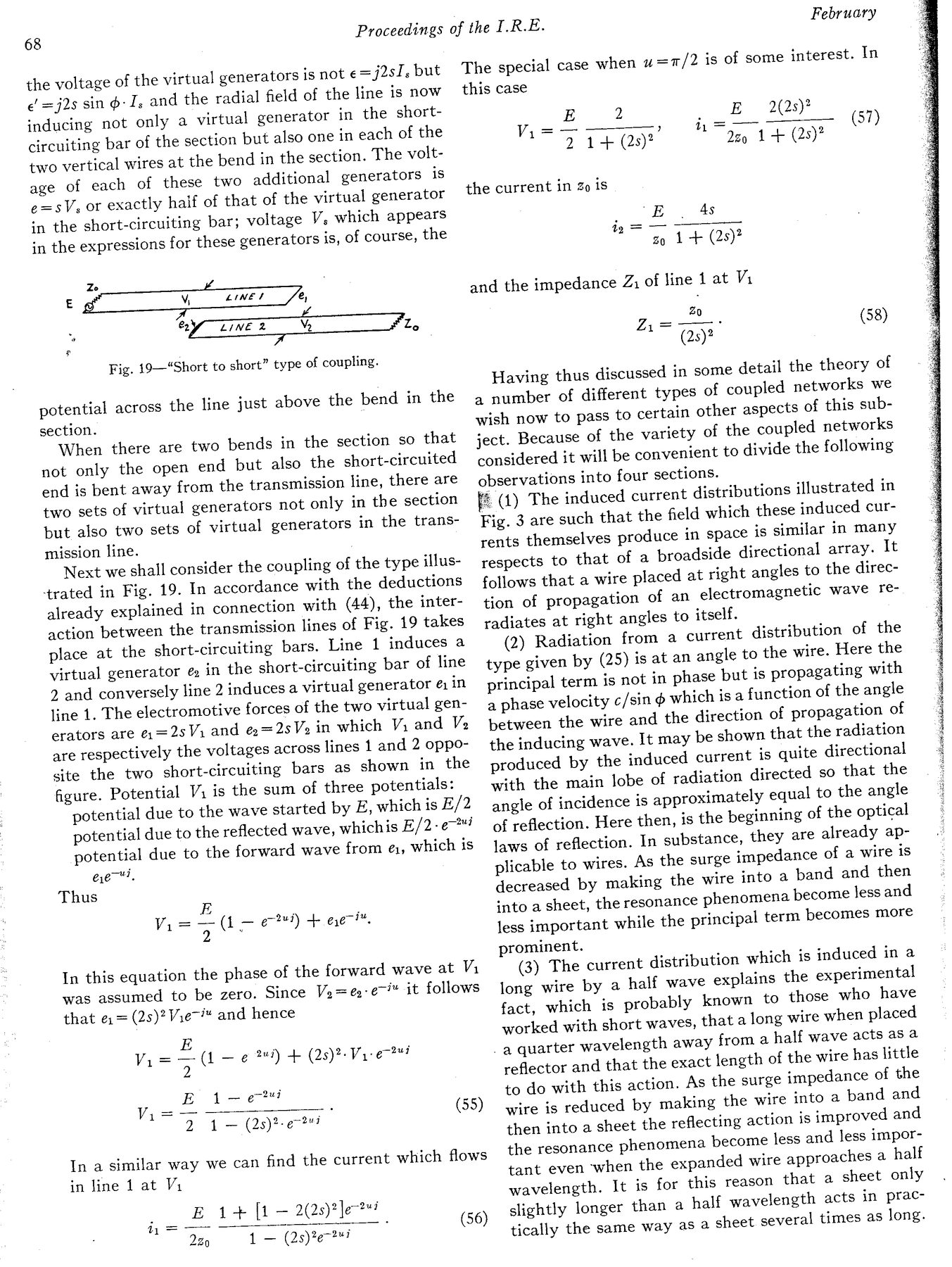
Fig. 19—“Short to short” type of coupling.

potential across the line just above the bend in the
section.

When there are two bends in the section so that
not only the open end but also the short-circuited
end is bent away from the transmission line, there are
two sets of virtual generators not only in the section
but also two sets of virtual generators in the trans-
mission line.

Next we shall consider the coupling of the type illus-
trated in Fig. 19. In accordance with the deductions
already explained in connection with (44), the inter-
action between the transmission lines of Fig. 19 takes
place at the short-circuiting bars. Line 1 induces a
virtual generator é in the short-circuiting bar of line
2 and conversely line 2 induces a virtual generator é1 in
line 1. The electromotive forces of the two virtual gen-
erators are ¢.=2sVi and @&=2s Vo in which V; and Ve
are respectively the voltages across lines 1 and 2 oppo-
site the two short-circuiting bars as shown in the
figure. Potential Vi is the sum of three potentials:

potential due to the wave started by E, which is E/2

potential due to the reflected wave, whichis E/2-e™

potential due to the forward wave from é1, which is
eet.
Thus
FE

Vi= 5 (1 — ef) + ee ™.

In this equation the phase of the forward wave at Vi
was assumed to be zero. Since Vo= eye it follows
that e: = (2s)?Vie~™ and hence

E
Vig "7 (1 —e 4) + (2s)? Vie"

E 1-8

Vi=— .
2 1 — (2s)?

(55)
In a similar way we can find the current which flows
in line 1 at V1

E 1+ [1 — 2(2s)?]e?™
220 1 — (2s)%e7?"? ,

h=

(56)

February
The special case when u=t/2 is of some interest. In
this case

E 2 _ £
— ) VW
2 1+ (25)?

_ 2(2s)?
Iz 1+ (2s)?

Vi = (57)

the current in Zo is
E As

ao 1 + (28)?

1g =

and the impedance Z, of line Lat Vi
(58)

Having thus discussed in some detail the theory of
a number of different types of coupled networks we
wish now to pass to certain other aspects of this sub-
ject. Because of the variety of the coupled networks
considered it will be convenient to divide the following
observations into four sections.
ye (1) The snduced current distributions illustrated in
Fig. 3 are such that the field which these induced cur-
rents themselves produce in space is similar in many
respects to that of a broadside directional array. It
follows that a wire placed at right angles to the direc-
tion of propagation of an electromagnetic wave re-
radiates at right angles to itself.

(2) Radiation from a current distribution of the
type given by (25) is at an angle to the wire. Here the
principal term is not in phase but is propagating with
a phase velocity c/sin @ which is a function of the angle
between the wire and the direction of propagation of
the inducing wave. It may be shown that the radiation
produced by the induced current is quite directional
with the main lobe of radiation directed so that the
angle of incidence is approximately equal to the angle
of reflection. Here then, is the beginning of the optical
laws of reflection. In substance, they are already ap-
plicable to wires. As the surge impedance of a wire is
decreased by making the wire into a band and then
into a sheet, the resonance phenomena become less and
less important while the principal term becomes more
prominent.

(3) The current distribution which is induced in a
long wire by a half wave explains the experimental
fact, which is probably known to those who have
worked with short waves, that a long wire when placed

_a quarter wavelength away from a half wave acts as a

reflector and that the exact length of the wire has little
to do with this action. As the surge impedance of the
wire is reduced by making the wire into a band and
then into a sheet the reflecting action is improved and
the resonance phenomena become less and less impor-
tant even ‘when the expanded wire approaches a half
wavelength. It is for this reason that a sheet only
slightly longer than a half wavelength acts in prac-

tically the same way as 2 sheet several times as long.