Alford2
Recognised text
Text below was produced by optical character recognition and may contain errors. Check it against the original.
1941

(4) Some of the coupled networks which have been
discussed have been very useful in solving certain
practical problems. Most of these practical applica-
tions so far have been made at high frequencies be-
tween about 5 megacycles and 140 megacycles. Below
5 megacycles these networks become rather large and
somewhat unwieldy. Above 140 megacycles there has
not been much need as yet for solving the particular
type of problems for which these networks are most
suited.

Broadly speaking, there are two types of service for
which coupled networks of the transmission line type
are particularly well adapted, (a) filters and (b) im-
pedance transformers.

(a) Coupled Network Filters.

A coupled section is a very simple and efficient rejec-
tion-type filter which transmits every frequency but
those to which the section is resonant. When the sec-
tion is coupled loosely, that is when s is small, the

vm

rn

—

&

Fig. 20—A coupled-section band-pass filter.

rejected band is narrow. When the network is coupled
tightly, the rejection band is relatively broad. Since
the bands of rejection occur when the section is 3A,
3, etc., long it is clear that these bands are very far
apart so that a section of this kind can generally be
used to reject just one frequency without disturbing
any other.

A coupled section when connected as shown in Fig.
20 acts as a band-pass filter which transmits only the
frequencies to which the section is tuned and rejects
all others. Again, as in the previous case, the bands at
which the section is in tune are very far apart so that
in practice a filter of this type may often be employed
to transmit just one frequency, others not coming
within the scope of the frequencies used, or rejected
by other elements in the circuit. When using the ar-
rangement of Fig. 20 it is ordinarily convenient to
select the points at which the line is connected to the
section in such a way that this line from the transmit-
ter is matched at the frequency which is passed by
the network. Several transmitters operating at differ-
ent frequencies may be connected to the same antenna,
each through its own section, so that all can deliver
their power into the line simultaneously without inter-
fering with each other. When the frequencies to be
delivered simultaneously to the same antenna are
separated by 6 per cent or so, it is best to employ two
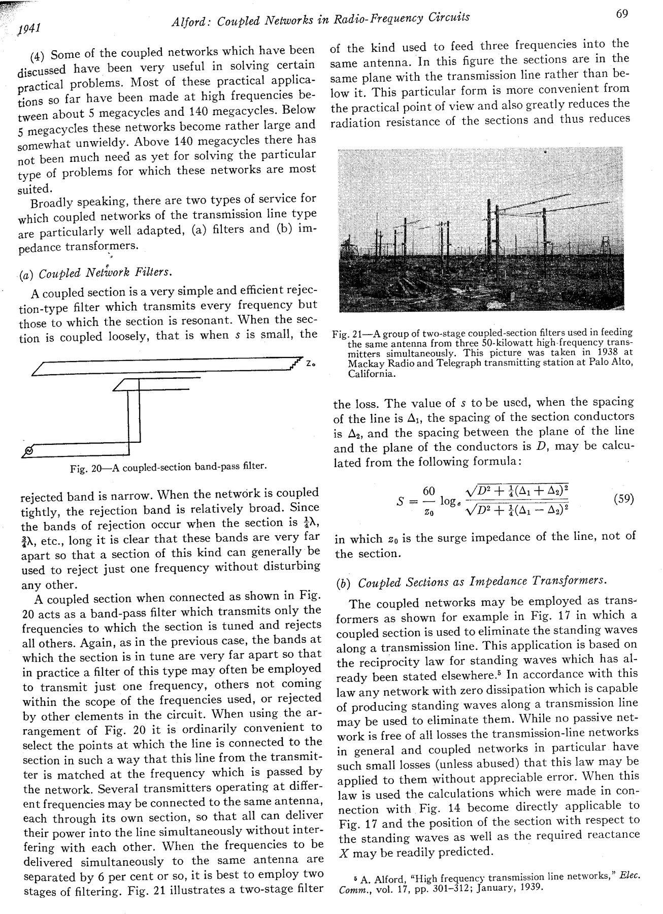
stages of filtering. Fig. 21 illustrates a two-stage filter

Alford: Coupled Networks in Radto- Frequency Circuits 69

of the kind used to feed three frequencies into the
same antenna. In this figure the sections are in the
same plane with the transmission line rather than be-
low it. This particular form is more convenient from
the practical point of view and also greatly reduces the
radiation resistance of the sections and thus reduces

Fig. 2I—A group of two-stage coupled-section filters used in feeding
the same antenna from three 50-kilowatt high-frequency trans-
mitters simultaneously. This picture was taken in 1938 at
Mackay Radio and Telegraph transmitting station at Palo Alto,
California.

the loss. The value of s to be used, when the spacing
of the line is Ay, the spacing of the section conductors
is Ay, and the spacing between the plane of the line
and the plane of the conductors is D, may be calcu-
lated from the following formula:

60 /D? + 3(Ai + As)?
S = — log.
Zo VD? + 4(Ai — 2)?

(59)

in which go is the surge impedance of the line, not of
the section.

(b) Coupled Sections as Impedance Transformers.

The coupled networks may be employed as trans-
formers as shown for example in Fig. 17 in which a
coupled section is used to eliminate the standing waves
along a transmission line. This application is based on
the reciprocity law for standing waves which has al-
ready been stated elsewhere.> In accordance with this
law any network with zero dissipation which is capable
of producing standing waves along a transmission line
may be used to eliminate them. While no passive net-
work is free of all losses the transmission-line networks
in general and coupled networks in particular have
such small losses (unless abused) that this law may be
applied to them without appreciable error. When this
law is used the calculations which were made in con-
nection with Fig. 14 become directly applicable to
Fig. 17 and the position of the section with respect to
the standing waves as well as the required reactance
X may be readily predicted.

8 A, Alford, “High frequency transmission line networks,” Elec.
Comm., vol. 17, pp. 301-312; January, 1939.