Construction
Recognised text
Text below was produced by optical character recognition and may contain errors. Check it against the original.
TRANSFORMER

TRANSFORMER

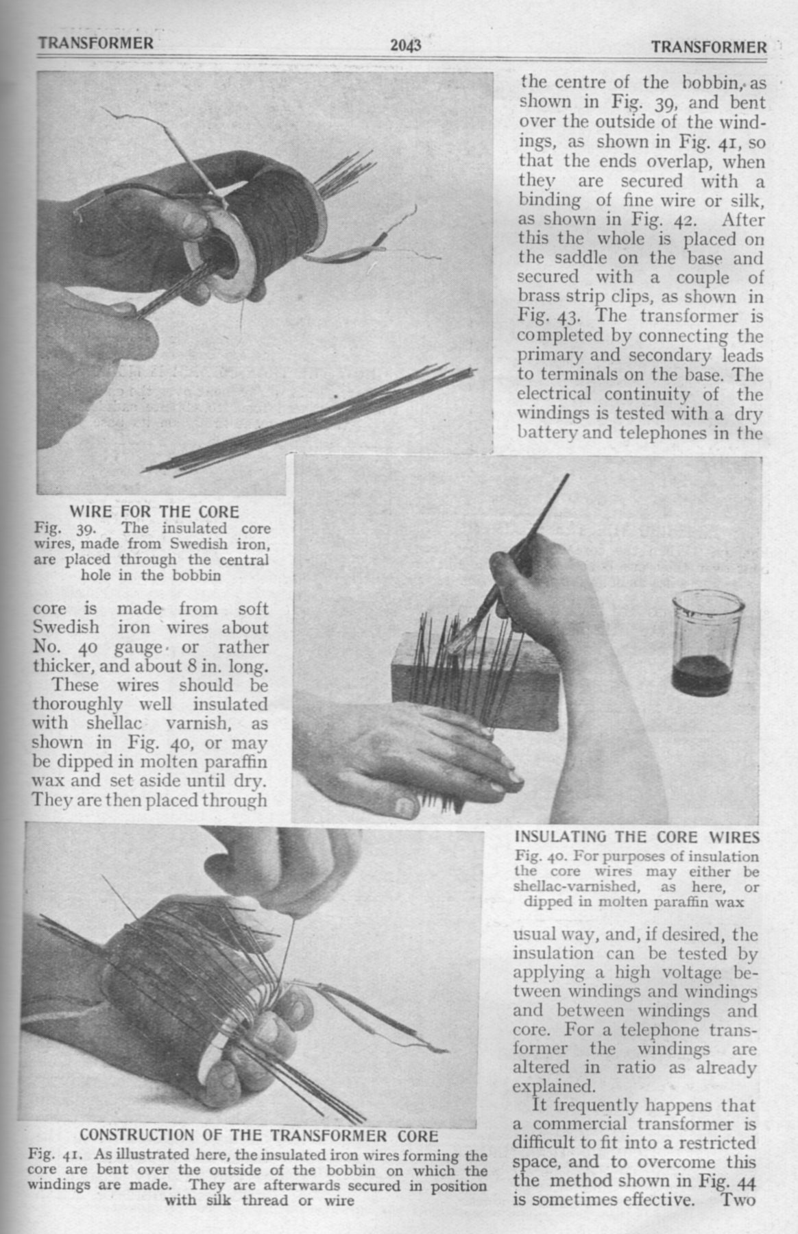
WIRE FOR THE CORE
Fig. 39. The insulated core
wires, made from Swedish iron,
are placed through the central
hole in the bobbin

core is made from soft
Swedish iron wires about
No. 40 gauge: or rather
thicker, and about 8 in. long.

These wires should be
thoroughly well insulated
with shellac’ varnish, as
shown in Fig. 40, or may
be dipped in molten paraffin
Wax and set aside until dry.
They are then placed through

with silk thread or wire

CONSTRUCTION OF THE TRANSFORMER CORE
Fig. 41. As illustrated here, the insulated iron wires forming the
core are bent over the outside of the bobbin on which the
windings are made. They are afterwards secured in position

the centre of the bobbin,as
shown in Fig. 39, and bent
over the outside of the wind-
ings, as shown in Fig. 41, so
that the ends overlap, when
they are secured with a
binding of fine wire or silk,
as shown in Fig. 42. After
this the whole is placed on
the saddle on the base and
secured with a couple of
brass strip clips, as shown in
Fig. 43. The transformer is
completed by connecting the
primary and secondary leads
to terminals on the base. The
electrical continuity of the
windings is tested with a dry
battery and telephones in the

1

INSULATING THE CORE WIRES
Fig. 40. For purposes of insulation
the core wires may either be
shellac-varnished, as here, or
dipped in molten paraffin wax

usual way, and, if desired, the
insulation can be tested by
applying a high voltage be-
tween windings and windings
and between windings and
core. For a telephone trans-
former the windings are
altered in ratio as already
explained.

It frequently happens that
a commercial transformer is
difficult to fit into a restricted
space, and to overcome this
the method shown in Fig. 44
is sometimes effective. Two