DOC Stanley 1937 1
Recognised text
Text below was produced by optical character recognition and may contain errors. Check it against the original.
THE TELECOMMUNICATION: JOURNAL OF AUSTRALIA

June, 1988

tion, the‘Age office, and engineering works.
ugh endeavours were made to establish
tical library, this phase of the society’s
forts did not meet with very great suc
4s an aid to this proposal, the P.M.Gi’s
nent was approached for a donation of
'. which, however, was refused.

710, Dr. Graham Bell visited Melbourne
pected the Central C.B. Exchange during
allation.’ He honoured the society as its
it a-function held in the Exchange just
o the formal opening. The photograph
ed shows the members of the party on
casion. Dr. Graham Bell and other dis-
ied personsges on the platform, however,
ot. been kindly treated by the photo-
r, and identification requires the use of a
ying glass.

growth and development of the society,

and its. progressive activities, particularly over
the last few years, must surely serve as a splen-
did ‘testimonial to the original sponsors of this
society, whose aims and objectives were so ideal-
istie, but are nevertheless now within: the limits
of achievement.

[Editor’s Note.—As it is desired to compile as
complete a history as possible of the early years
of the society, members are specially invited to
furnish any additional information that may be
in their possession. In particular, a complete
copy of Mr. Jenvey’s inaugural address and early
papers published by the society would be. wel-
come.

We are indebted to Messrs. R. F. Archer,
E. A. Batty, and H. J. Rutherford, for kindly
furnishing the information on which these notes
have been based, and for the loan of the photo-
graphs.]

THE NEW MELBOURNE TRUNK EXCHANGE

iter issues of the Journal there will be
. giving the many interesting features of
aipment and the installation of this im-
; exchange, but at this stage a general
of the facilities to be provided may be
syest, An order has been placed with
. Siemens Bros:, London, for the appara-
the trunk exchange and the voice fre-
signalling: equipment in country centres.
will also be desks specially equipped to
cpeditious distribution, pricing and sorting
1 dockets, the positions having inter-
ting pneumatic tubes.
, from Metropolitan subscribers for Trunks
ypear on the Demand positions, of which
vill be. 54, the calls being queued up in the
of arrival. The calls, can be answered
-number of positions on which the number
ting. calls will be indicated. By throwing
the telephonist will be automatically al-
the first callin the queue. Should any call
iting attention beyond a prescribed period,
) seconds, the display lamp flickers until
| answering conditions are re-established.

elephonist will set up the eode for the.

ad trunk line on a key-set sender and by
eration of appropriate keys the connection
x completed through the switches. Timing
call is started manually but will be com-

automatically ‘under the control of the
- gubseriber’s switchhook. Any of the
ms in the Demand suite can readily be
ted to delay working when required. If
affic offering to a country centre precludes
issibility of giving service on demand it is
ary to handle the traffic to that centre on
y basis, in which case the Demand tele-
s+ simply books the call and the docket
ted to the position set aside to complete
ealls when the required trunk is available.
s from country centres will be direct
1 over the voice frequency channels to the

Metropolitan automatic equipment over incoming
selectors in the Trunk exchange. Calls incoming
in this way for another trunk line will be direct-
ed to “Through positions,” six of which will be
installed, and. the telephonist will set up the
connection in the same way as on the Demand
position, .

Bighteen interstate positions are to be in-
stalled initially for handling incoming and out-
going interstate traffic. The interstate circuits
are connected to the positions through the
switches but are then held during the busy hours
of the day and are worked on what is known as
a “back to back” basis, that is, a telephonist at
each end has exclusive use of two trunk lines
and they arrange the traffic in either direction
as desired. The wanted subscribers are obtained
by means of the keyset senders and are con-
nected as required to the Trunk lines by means
of coupling keys. In addition there will be five
Trunk Enquiry and three Suspense positions, the
latter taking over traffic which cannot be dealt
with owing to the called subseriber or a par-
ticular person not being in attendance.

All the positions are of the cordless type, the
eoutrol being by means of keys and press
buttons. The equipment. will be rack mounted,
a particular feature is that the finders and
selectors will be the motor uniselector type de-
scribed in Paper No. 25 issued by the Society.
A further point of particular interest is that
hybrid coils on the switchboard side of all
carrier channels and lines equipped. with terminal
amplifiers will be automatically switched on a
four wire basis, suitable pad switching control
being provided as necessary.

Mr. McHenry, of the Chief Engineer’s Branch,
is at present in England co-operating with the
contractors’. designing engineers. to ensure that
the equipment supplied will meet local conditions
in every respect.

June, 1988

THE TELECOMMUNICATION JOURNAL OF. AUSTRALIA

Page &

ULTRA
VICTORIA AND TASMANIA

Introduction: This article describes experi-
ments which have been carried out on the pro-
pagation of radio frequencies in the vicinity of
40 megacycles per second (wave length 7.5
metres). The object of the experiments was. to
obtain information of the propagation character-
istics over a nonr-optical path with a view to
finding the power and aerial requirements needed
for ultra high frequency systems. The path
chosen for the experiments was from Victoria to
Tasmania where the transmission path was com-
pletely over sea water.

The details of the work involved and the re-
sults obtained are described hereunder.

Direction of Transmission: The direction of
transmission was chosen as Victoria to Tasmania,
the transmitter being in Victoria and the receiver
in Tasmania. It was expected, from the reci-
procal theorem, that propagation in both direc-
tions would be similar. This theorem due to
John R. Carson, states: If an electromotive force
E inserted in antenna 1 causes a’ current I to
flow at a certain point in antenna 2, then the
electromotive force E inserted at this point in
the second antenna will produce the same current
(both in magnitude and phase) at the point in
antenna 1 where the voltage E was originally
applied.

This theorem fails only when propagation is
appreciably affected by an ionised medium in the
presencé of a magnetic field, and thus since the
ultra-high frequencies are not propagated in the
ionosphere the theorem should hold in the case
under consideration.

General: The field intensity received at ultra
high frequencies depends upon various factors as
follows :—

(a) Distance between transmitter and receiver.
The intensity decreases with increasing distance;
; (b) Height of transmitter and receiver. The
intensity Increases if the height of the trans-
mitter or receiver is increased, other things re-
maining equal;

(ce) Frequency: In general the field intensity
decreases as the frequency is raised (for equal
power and aerial arrays proportional in size to
the wave length) ;

(d) Aerial array. The intensity increases as
the area of the aerial array is increased,

In addition to the above, the propagation is
effected by such uncontrollable factors as :—

(a). Season ;

(b) Time of day;

(c) Weather conditions, state of the atmos-
phere, etc.; but the extent of the variation due
to these causes is unknown. It is hoped, how-
ever, that quantitative results may be. obtained

HicgH FREQUENCY EXPERIMENTS BETWEEN

D. McDonald, B.Sc.

from a continuation of the experiments outlined
below.

_ Selection of. Sites: With the above considera-
tions in view the coast lines of Victoria and
Tasmania were investigated. The optimum com-
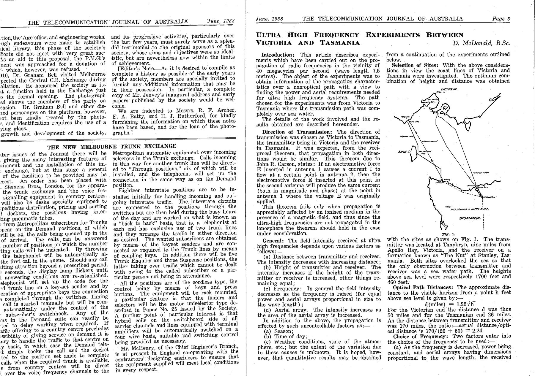
bination of height and distance was obtained

VICTORIA.
Coneoy

None:
(HS DAMNING 13 W8PTO LSE,

{
TASMANIA.

Fig. 1.

with the sites as shown on Fig. 1. The trans-
mitter was located at Tanybryn, nine miles from
Apollo | Bay,. Victoria, and the receiver on a
formation known as “The Nut” at Stanley, Tas-
mania. Both sites overlooked the sea so that
the only obstruction between. transmitter and
receiver was a sea water path. The heights
above sea level were respectively 1700 feet and
460 feet.

Optical Path Distances: The approximate dis-
tance to the visible horizon from a point h feet
above sea level is given by:—

d(miles) = 1.22Vh-
For the Victorian end the distance d was thus
50 miles and for the Tasmanian end 26 miles.
As the distance between transmitter and receiver
was 170 miles, the ratio:—actual distance /opti-
eal distance is 170/(26 + 50) = 2.24.

Choice of Frequency: Two factors enter into
the choice of the frequency to be used:—

(a) As the frequency is decreased, power being.
constant, and aerial arrays having dimensions
proportional to the. wave length, the received

° +

Page 6

June, 1938

signal due to the

the indirect wave i

and the signal mor _

remote from the tr, asmitter. “ine. D
critical: frequency ‘above / which the ere
does not return the + earth. Th
Wave causes \ Yeceiver aiid” mar
cause int, ‘vices if propagat’
- wa

auses a deert

> the grou,
‘es, causix
it y of inte
fe’ . .
apromise in
the \, tis case the
frequy, 8 of curves
4
;
§
=
2 t
“20;
2)
=r
a
aon
3
= 50m |e
a “hone
2 Ne
3”
SJ
2
-100|
o 100 200
Distance - Miles.
Fig. 2,

such as shown in Figs. 2 and 8. Fig. 2 shows
the field intensity expected at various frequencies
for a radiated power of 1 kilowatt, the trans-
mitter being 1700 feet above sea level and the
receiver at sea level. Fig. 8 shows the gain
obtained due to raising the receiver above sea
level, The gain is given in decibels ag a function
of bha~§, where.h is the height above sea level
in metres and , is the wavelength in metres.

From Figs. 2 and 3 for a height of trans-
mitter of 1700 feet above sea level and of re-
ceiver 460 feet above gea level, distance. 170
miles, the received field intensities at frequencies
80, 37.5 and 50 megaecycles per sec, are respec-
tively 71, 75.5 and 81.5 decibels below 1 millivolt
per metre. -

"A frequency of approximately 40 megacycles
per sec. was chosen as it was considered that the
indirect wave at this frequency would be negli-
‘gible, and the received signal would be appre-
ciably higher than that for 50 megacycles per
sec,

“ON JOURNAL OF AUSTRALIA

sirect’

Aerial Arrays: For normal broadcast frequen-
cies 550-1500 kilocycles per second (wavelength
“45200 metres) the use of directional aerial

‘+ usually not practicable because of the

T
nee ma
_
a s0mC eg Ome
¢ 30
£ Lame
£
3
@
20 A
5 ‘
a
a
rr)
° 10 20 30 40 50 60
avs
Fig. 3,

large spacing needed between elements of the
array. As the spacing needed is usually of the
order of one half wavelength, the required space
would be large.

In the ultra high frequency range, however,
the use of directional arrays becomes practicable
and desirable, because the overall dimensions of
an array of several wavelengths extent are re-
latively small. : .

At the time of this experiment, no experience
was available as to the relative advantages of
horizontal and vertical aerials for conditiong simi-

Fig. 4,

lar to the case under consideration, and it was
decided to erect both horizontal and vertical
arrays. The general principles of an array may
be seen by reference to Fig. 4.

“In Fig. 4, a, b, ¢, d, etc, are radiators Separ-
ated by a definite fraction of a wavelength, the
currents in the various radiators bearing some
simple phase relationship. In the arrays used

June, 1938 THE TELECOMMUNICATION

JOURNAL OF. AUSTRALIA Page 7

the currents in. all elements. were in phase and

’ the radiators spaced one half-wavelength apart

between centres. The function of the array is
to augment the radiation in a certain desired
direction at the expense of radiation in other
directions. In Fig. 4 if N = the number of
radiators and n¥ is the spacing between adjacent
radiators, the currents in all radiators being in
phase, the field intensity in the horizontal plane
at an angle ¢ to the normal to the array is given

by :— .
y sin (N7nsin 4)

Es = E
sin (an sin ¢)
where E = field intensity due to one radiator.
In Fig. 5 is shown a polar diagram in the
horizontal plane of (a) a single half wave verti-
eal aerial and (b) eight half wavelength aerials
fed in phase and spaced one half wavelength

(b) @)

*
“Radiators

\
a:
f
iA
Fig. 5.

apart in the horizontal plane. The gain, of the
array as. shown in the maximum direction | is
10 db over a single half wave aerial. By placing
a similar set of radiators one quarter wavelength
behind the array, radiation in a backward diréc-
tiow is cancelled and the frontward radiation is
increased by 8 db, giving a total gain over a
single half wave radiator of 18 db.

Fig. 6 shows a layout of the aerials at the

‘ transmitting site, both horizontal andi vertical

arrays. being shown. The shape of the radiation
diagram for the horizontal array is essentially
similar to that of the vertical array shown in
Fig. 5. The aerial arrays at receiving and trans-

" mitting sites are similar, and were connected to

the huts by open wire transmission lines.
Transmitter: The transmitter consisted of an
oscillator using 808 type tubes, the frequency
being controlled by resonant lines arranged in a
spiral form to reduce the required space. The
transmitter was modulated by a unit using two

800 type tubes in the final stage, and either
continuous tone or speech could be used.

Power supply was obtained from a generator
driven by a single cylinder petrol engine; the
generator having windings for 3000 volts and 16
volts gave both the filament and plate supplies.
A plate voltage of 1500 volts was used for the
oscillator, the output under the operating condi-

Horizontal Array

|
|

L

Vertical Array
Fig. 6.

tions being approximately 200 watts.. Due to
the gain of the array. in the .desired direction,
the radiation was equivalent to 13 db above 200
watts (4 kilowatts) from a single half wave
radiator. . :
Receiver: Two receivers were used:— _
(1) A super-regenerative receiver (commercial
model) ; oo
(2) A super-heterodyne receiver (built in the
Research Laboratories).
Quantitative measurements of received signal
were made by (a) measuring the change in plate
current of the superheterodyne receiver with
change of signal; and (b) measuring-the reduc:

srneey Tt aur
CONT OPE .

Fig. 7.

tion in noise level of the super-regenerative re-
ceiver with increase of signal. Fig. 8 shows the
relationship between signal input and noise level
in a super-regenerative receiver.

For communication purposes a telephone line
was erected between the receiver hut and the
Stanley Post Office. The wires were of 200 lb.
copper and were used to transmit A.C. power to
operate the receivers. Fig. 7 shows the arrange-
ment for supplying .A.C. power over the lines;