Gillies 3
Recognised text
Text below was produced by optical character recognition and may contain errors. Check it against the original.
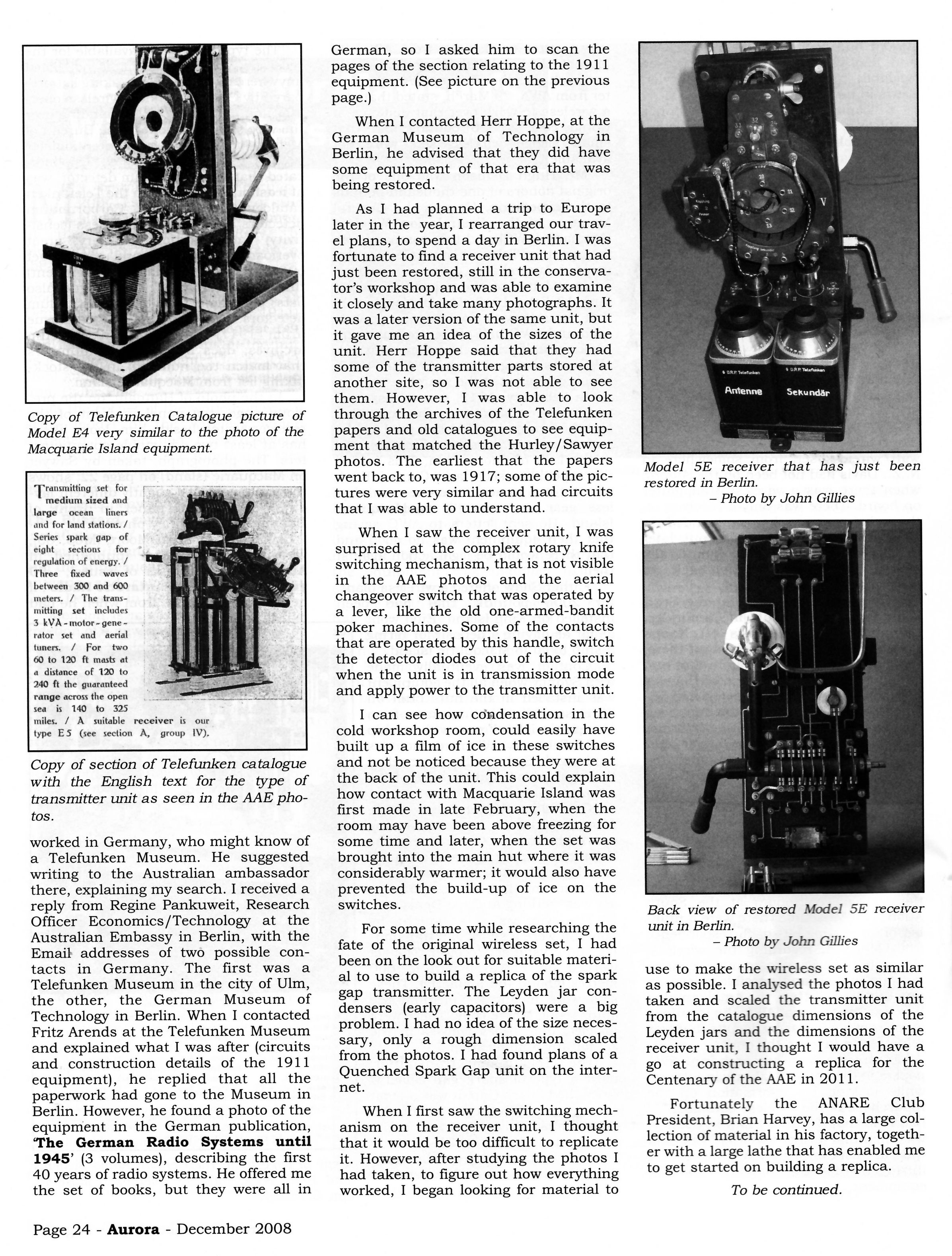
Copy of Telefunken Catalogue picture of
Model E4 very similar to the photo of the
Macquarie Island equipment.

Tsommitting set for

medium sized and
large ocean __ liners
and for land stations. /
Series spark gap of
eight sections —_ for
regulation of energy. /
Three fixed waves
between 300 and 600
meters. / The trans-
mitting set includes
3 kVA- motor - gene ~
rator set and aerial
tuners. / For two
60 to 120 ft masts at
a distance of 120 to
240 ft the guaranteed
range across the open
sea is 140 to 325
miles. / A suitable receiver is our
type ES (see section A, group IV).

Copy of section of Telefunken catalogue
with the English text for the type of
transmitter unit as seen in the AAE pho-
tos.

worked in Germany, who might know of
a Telefunken Museum. He suggested
writing to the Australian ambassador
there, explaining my search. I received a
reply from Regine Pankuweit, Research
Officer Economics/Technology at the
Australian Embassy in Berlin, with the
Email addresses of two possible con-
tacts in Germany. The first was a
Telefunken Museum in the city of Ulm,
the other, the German Museum of
Technology in Berlin. When I contacted
Fritz Arends at the Telefunken Museum
and explained what I was after (circuits
and construction details of the 1911
equipment), he replied that all the
paperwork had gone to the Museum in
Berlin. However, he found a photo of the
equipment in the German publication,
‘The German Radio Systems until
1945’ (3 volumes), describing the first
40 years of radio systems. He offered me
the set of books, but they were all in

Page 24 - Aurora - December 2008

German, so I asked him to scan the
pages of the section relating to the 1911
equipment. (See picture on the previous

page.)

When I contacted Herr Hoppe, at the
German Museum of Technology in
Berlin, he advised that they did have
some equipment of that era that was
being restored.

As I had planned a trip to Europe
later in the year, I rearranged our trav-
el plans, to spend a day in Berlin. I was
fortunate to find a receiver unit that had
just been restored, still in the conserva-
tor’s workshop and was able to examine
it closely and take many photographs. It
was a later version of the same unit, but
it gave me an idea of the sizes of the
unit. Herr Hoppe said that they had
some of the transmitter parts stored at
another site, so I was not able to see
them. However, I was able to look
through the archives of the Telefunken
papers and old catalogues to see equip-
ment that matched the Hurley/Sawyer
photos. The earliest that the papers
went back to, was 1917; some of the pic-
tures were very similar and had circuits
that I was able to understand.

When I saw the receiver unit, I was
surprised at the complex rotary knife
switching mechanism, that is not visible
in the AAE photos and the aerial
changeover switch that was operated by
a lever, like the old one-armed-bandit
poker machines. Some of the contacts
that are operated by this handle, switch
the detector diodes out of the circuit
when the unit is in transmission mode
and apply power to the transmitter unit.

I can see how condensation in the
cold workshop room, could easily have
built up a film of ice in these switches
and not be noticed because they were at
the back of the unit. This could explain
how contact with Macquarie Island was
first made in late February, when the
room may have been above freezing for
some time and later, when the set was
brought into the main hut where it was
considerably warmer; it would also have
prevented the build-up of ice on the
switches.

For some time while researching the
fate of the original wireless set, I had
been on the look out for suitable materi-
al to use to build a replica of the spark
gap transmitter. The Leyden jar con-
densers (early capacitors) were a big
problem. I had no idea of the size neces-
sary, only a rough dimension scaled
from the photos. I had found plans of a
Quenched Spark Gap unit on the inter-
net.

When I first saw the switching mech-
anism on the receiver unit, I thought
that it would be too difficult to replicate
it. However, after studying the photos I
had taken, to figure out how everything
worked, I began looking for material to

Antenne Sekundar

Model 5E receiver that has just been

restored in Berlin.
— Photo by John Gillies

Back view of restored Model 5E receiver
unit in Berlin.
— Photo by John Gillies

use to make the wireless set as similar
as possible. I analysed the photos I had
taken and scaled the transmitter unit
from the catalogue dimensions of the
Leyden jars and the dimensions of the
receiver unit, I thought I would have a
go at constructing a replica for the
Centenary of the AAE in 2011.

Fortunately the ANARE Club
President, Brian Harvey, has a large col-
lection of material in his factory, togeth-
er with a large lathe that has enabled me
to get started on building a replica.

To be continued.