Gillies4
Recognised text
Text below was produced by optical character recognition and may contain errors. Check it against the original.
Building a Replica of the Wireless Set used by
Douglas Mawson’s 1911 Australasian Antarctic Expedition

Continuation of article, ‘The Search
for Mawson’s Wireless Sets’,
from Aurora, December, 2008.

In the article titled ‘The Search for
Mawson’s Wireless Sets’, which I wrote
for Aurora, December, 2008, (Pages 22
to 24), I made some errors. On Page 22,
I wrote that, by my observation during a
visit to the hut in December, 2005, the
bunks of Herbert Dyce-Murphy, Leslie
Whetter and Walter Hannam were miss-
ing.

In later years, excavation of the ice in
that area has exposed Dyce-Murphy’s
bunk, with the writing in the wall,
‘Wireless 1913’. There is still more exca-
vation to be done in that area, but there
were some electrical wires among the
ice.

I had wondered why no photographs
of the radio in that position existed.
There: were. other . people -on. ‘the
Australasian Antarctic Expedition (AAE)
with cameras, but the only photographs
of the hut interior were taken by Frank
Hurley with the flash equipment he had.
When Hurley arrived, in 1913, the wire-
less equipment had been packed up for
return to Australia a month before
Aurora arrived to take them home,
explaining the lack of other photographs
of the wireless.

The bunk of Herbert Dyce-Murphy
was just inside the door into the main
hut from the workshop. Douglas
Mawson and Dyce-Murphy were the
only two people to have single level
bunks.

Just what parts of the wireless were |

brought into the main hut, I am not sure
of, at the moment. If the transmitter sec-
tion was shifted there as well, there
would have been considerable rewiring
of the power system.

As the aerial changeover switch is on
the receiver unit, there must have been
quite a few wires through the wall into
the workshop.

Because the receiver did not need
any power to operate it, Sydney Jeffryes
could have listened on the headphones,
while lying on the bunk used by Leslie
Whetter in 1912.

BUILDING THE REPLICA WIRELESS
I have written an article about build-

ing the replica for the Historical Radio
Society of Australia. It is being pub-

lished in their journal, Radio Waves, ©

over several issues. This account is a
shorter, less technical version, and not
all in chronological order.

The Beginning

The first item I started work on was
the ‘quenched spark gap’ unit. I had

Page 14 - Aurora - June 2012

— By John Gillies

previously downloaded, from the inter-
net, a description of how to make one.

Brian Harvey (M77, Q79, C83), then
ANARE Club president, had some large
sheets of copper. I was able to cut them
into rough circular shapes, then bolt
them to a jig to hold them all together, so
they could be turned in the lathe to
make them round and all the same size,
for the heat sink fins. These dissipate
the heat caused by the spark action.
Brian also had some large copper rod
that I turned to make the electrodes.
These are enclosed inside large mica
washers, that the spark jumped
between.

Copper electrodes for the spark gap section.

Spark gap unit assembled with large
heat sink fins. Mica washers can be seen
between the electrodes.

I had to have the washers made by
a manufacturer in Melbourne, Victoria.

The ‘quenched spark gap’ unit is
mounted in an insulating frame. The
end sections are cut from a sheet of
paper bakelite that Brian also had in his
workshop. There is a tension screw at
one end to keep the gaps inside the mica
washers airtight to reduce oxidisation of
the electrodes.

Leyden jars and transmitter coils
The Leyden jars, an early form of
capacitors, took a few iterations. Firstly
glass coffee jars, which cracked in the
cold weather. Then to large glass tubes
which have thin brass sheets fixed
inside and around the outside before
being inserted into 100 mm brass tubes,
to make them more robust. The tubes
had a circular ‘finger contact’ at the
base to make contact with the outside
brass sheet. The four Leyden jars were

Four of the brass tubes, containing the
Leyden jars, mounted in the transmitting
section frame.

mounted in a frame and clamped into
position, with the outsides of all the
tubes connected to the frame. The tubes
have wooden caps, with spring fingers
that make contact with the brass sheet
inside the tube. They can then be con-
nected together to make different values
of capacitance for the tuned circuit that
selects the frequency to be broadcast.
These actually work by storing the
electrical charge as a stress in the glass.
The other part of the tuning circuit,
seen in Hurley’s photograph and the
German Telefunken catalogue pictures,
is a spiral coil mounted on the frame of
the transmitter unit. To make this look
realistic I had some 13 mm diameter
copper waterpipe, flattened by a panel-

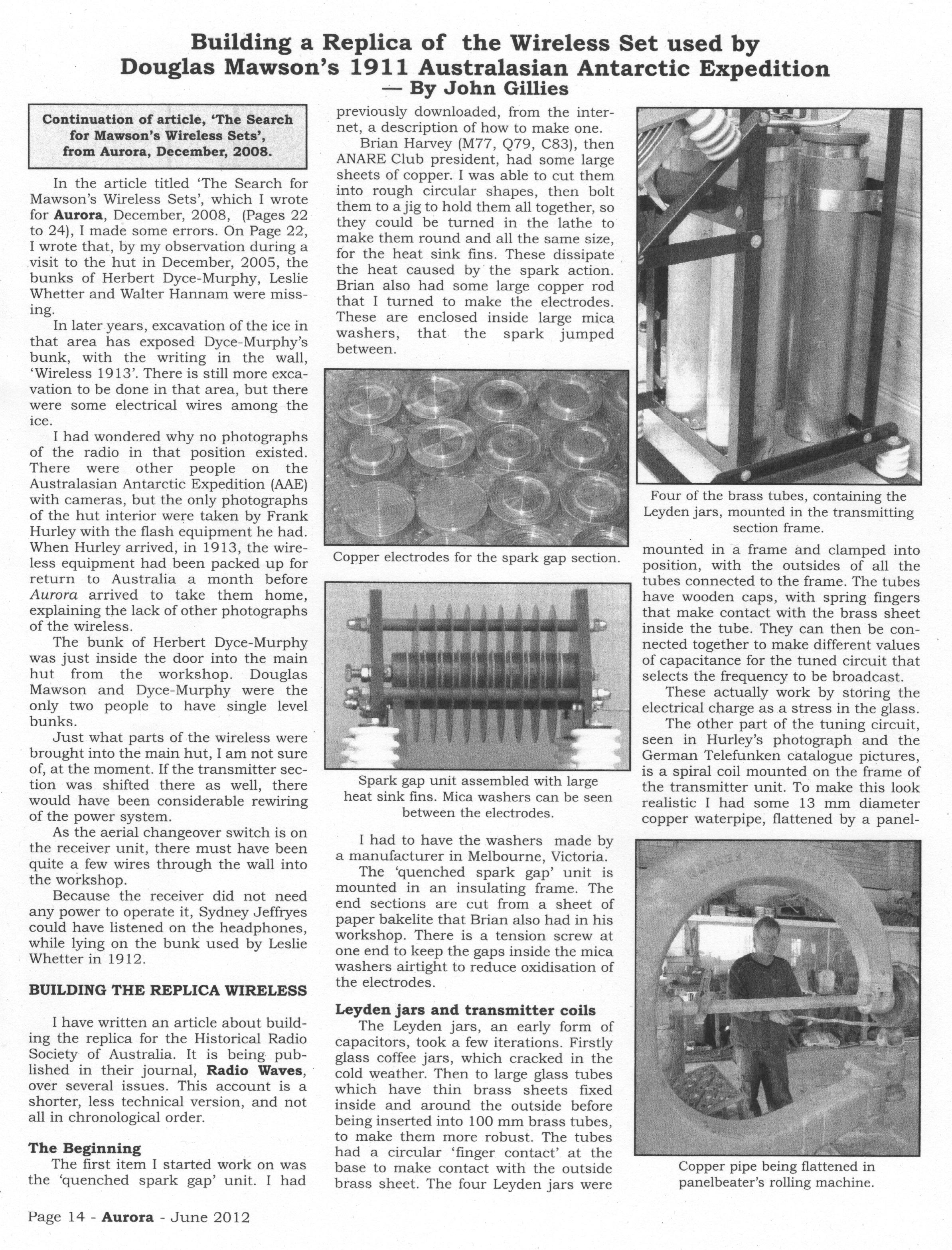
Copper pipe being flattened in
panelbeater’s rolling machine.