Gillies5
Recognised text
Text below was produced by optical character recognition and may contain errors. Check it against the original.
beater’s rolling machine, until it was
about 2.5 mm thick. It was then
annealed to make it soft enough to be
wound into a tight spiral.

Initially I made the temporary coil
formers out of medium density fibre-
board (MDF), but they were not solid
enough when grooves were routed into
them, to hold the copper pipe in the spi-
ral shape. However this proved that the
idea would work. Brian Harvey had
some more paper bakelite sheet that I
was able to shape into six-arm formers
for this coil, and the coils for the vari-
ometer, part of the antennae matching
unit.

Jig to rout the grooves in the coil formers.

I made a jig to hold the former
shapes on a sliding platform with the
router fixed above it. A long screw
advanced the platform holding the for-
mer 2 mm for one turn, as the former
was rotated 60 degrees, making grooves
12 mm apart, in each arm of the face of
the former.

The formers were bolted to another
sheet of wood and the copper strip
wound from the tight inside diameter to
the larger outside. Each turn was held
in place by a lot of bolts and washers
until the other face of the former was
placed on top, and the copper strip

Flattened copper strip held temporarily
in spiral coil shape.

manipulated into all the matching
grooves. When the former sides were
fixed together, all the temporary holding
bolts were removed.

From the circuits I had found in the
German Telefunken catalogues, I was

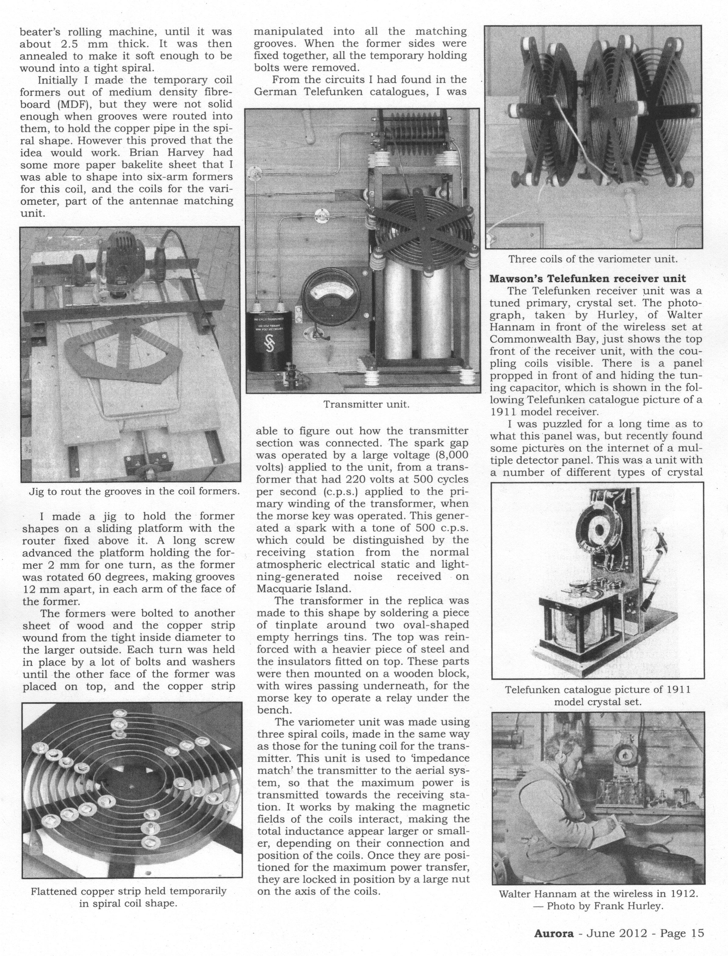
Transmitter unit.

able to figure out how the transmitter
section was connected. The spark gap
was operated by a large voltage (8,000
volts) applied to the unit, from a trans-
former that had 220 volts at 500 cycles
per second (c.p.s.) applied to the pri-
mary winding of the transformer, when
the morse key was operated. This gener-
ated a spark with a tone of 500 c.p.s.
which could be distinguished by the
receiving station from the normal
atmospheric electrical static and light-
ning-generated noise received on
Macquarie Island.

The transformer in the replica was
made to this shape by soldering a piece
of tinplate around two oval-shaped
empty herrings tins. The top was rein-
forced with a heavier piece of steel and
the insulators fitted on top. These parts
were then mounted on a wooden block,
with wires passing underneath, for the
morse key to operate a relay under the
bench.

The variometer unit was made using
three spiral coils, made in the same way
as those for the tuning coil for the trans-
mitter. This unit is used to ‘impedance
match’ the transmitter to the aerial sys-
tem, so that the maximum power is
transmitted towards the receiving sta-
tion. It works by making the magnetic
fields of the coils interact, making the
total inductance appear larger or small-
er, depending on their connection and
position of the coils. Once they are posi-
tioned for the maximum power transfer,
they are locked in position by a large nut
on the axis of the coils.

Three coils of the variometer unit.

Mawson’s Telefunken receiver unit

The Telefunken receiver unit was a
tuned primary, crystal set. The photo-
graph, taken by Hurley, of Walter
Hannam in front of the wireless set at
Commonwealth Bay, just shows the top
front of the receiver unit, with the cou-
pling coils visible. There is a panel
propped in front of and hiding the tun-
ing capacitor, which is shown in the fol-
lowing Telefunken catalogue picture of a
1911 model receiver.

I was puzzled for a long time as to
what this panel was, but recently found
some pictures on the internet of a mul-
tiple detector panel. This was a unit with
a number of different types of crystal

Telefunken catalogue picture of 1911
model crystal set.

Walter Hannam at the wireless in 1912.
— Photo by Frank Hurley.

Aurora - June 2012 - Page 15