Gillies6
Recognised text
Text below was produced by optical character recognition and may contain errors. Check it against the original.
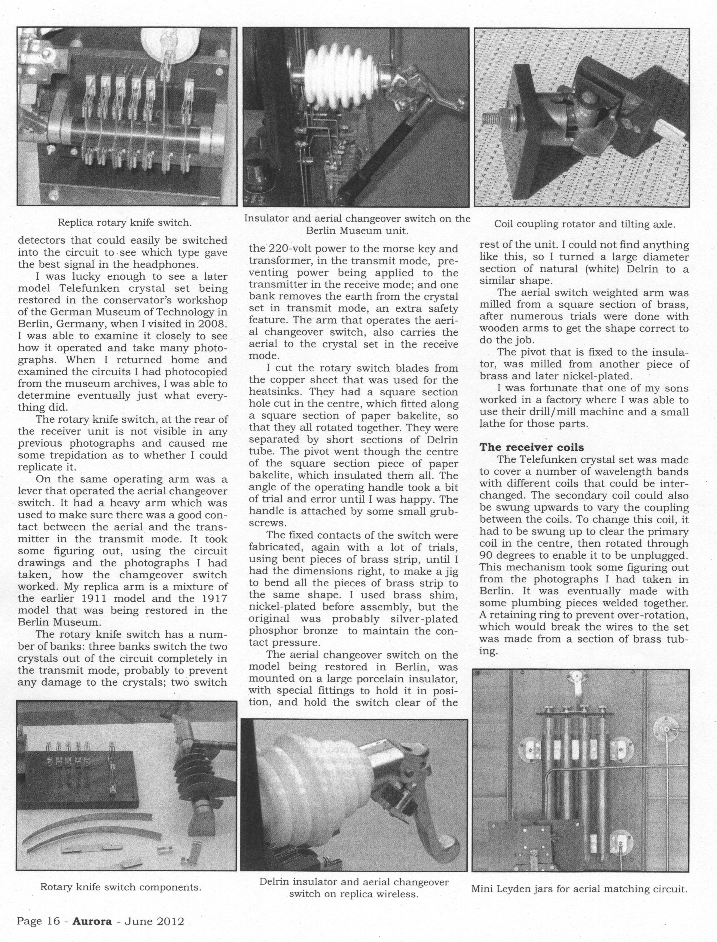
Replica rotary knife switch.

detectors that could easily be switched
into the circuit to.see which type gave
the best signal in the headphones.

I was lucky enough to see a later
model Telefunken crystal set being
restored in the conservator’s workshop
of the German Museum of Technology in
Berlin, Germany, when I visited in 2008.
I was able to examine it closely to see
how it operated and take many photo-
graphs. When I returned home and
examined the circuits I had photocopied
from the museum archives, I was able to
determine eventually just what every-
thing did.

The rotary knife switch, at the rear of
the receiver unit is not visible in any
previous photographs and caused me
some trepidation as to whether I could
replicate it.

On the same operating arm was a
lever that operated the aerial changeover
switch. It had a heavy arm which was
used to make sure there was a good con-
tact between the aerial and the trans-
mitter in the transmit mode. It took
some figuring out, using the circuit
drawings and the photographs I had
taken, how the chamgeover switch
worked. My replica arm is a mixture of
the earlier 1911 model and the 1917
model that was being restored in the
Berlin Museum.

The rotary knife switch has a num-
ber of banks: three banks switch the two
crystals out of the circuit completely in
the transmit mode, probably to prevent
any damage to the crystals; two switch

Rotary knife switch components.

Page 16 - Aurora - June 2012

Insulator and aerial changeover switch on the
Berlin Museum unit.

the 220-volt power to the morse key and
transformer, in the transmit mode, pre-
venting power being applied to the
transmitter in the receive mode; and one
bank removes the earth from the crystal
set in transmit mode, an extra safety
feature. The arm that operates the aeri-
al changeover switch, also carries the
aerial to the crystal set in the receive
mode.

I cut the rotary switch blades from
the copper sheet that was used for the
heatsinks. They had a square section
hole cut in the centre, which fitted along
a square section of paper bakelite, so
that they all rotated together. They were
separated by short sections of Delrin
tube. The pivot went though the centre
of the square section piece of paper
bakelite, which insulated them all. The
angle of the operating handle took a bit
of trial and error until I was happy. The
handle is attached by some small grub-
screws.

The fixed contacts of the switch were
fabricated, again with a lot of trials,
using bent pieces of brass strip, until I
had the dimensions right, to make a jig
to bend all the pieces of brass strip to
the same shape. I used brass shim,
nickel-plated before assembly, but the
original was probably silver-plated
phosphor bronze to maintain the con-
tact pressure.

The aerial changeover switch on the
model being restored in Berlin, was
mounted on a large porcelain insulator,
with special fittings to hold it in posi-
tion, and hold the switch clear of the

Delrin insulator and aerial changeover
switch on replica wireless.

Coil coupling rotator and tilting axle.

rest of the unit. I could not find anything
like this, so I turned a large diameter
section of natural (white) Delrin to a
similar shape.

The aerial switch weighted arm was
milled from a square section of brass,
after numerous trials were done with
wooden arms to get the shape correct to
do the job.

The pivot that is fixed to the insula-
tor, was milled from another piece of
brass and later nickel-plated.

I was fortunate that one of my sons
worked in a factory where I was able to
use their drill/mill machine and a small
lathe for those parts.

The receiver coils

The Telefunken crystal set was made
to cover a number of wavelength bands
with different coils that could be inter-
changed. The secondary coil could also
be swung upwards to vary the coupling
between the coils. To change this coil, it
had to be swung up to clear the primary
coil in the centre, then rotated through
90 degrees to enable it to be unplugged.
This mechanism took some figuring out
from the photographs I had taken in
Berlin. It was eventually made with
some plumbing pieces welded together.
A retaining ring to prevent over-rotation,
which would break the wires to the set
was made from a section of brass tub-
ing.

Mini Leyden jars for aerial matching circuit.