Hedgehog
Recognised text
Text below was produced by optical character recognition and may contain errors. Check it against the original.
|= ver? |

HEAVISIDE LAYER

1093 _

HEISING MODULATION

given in this Encyclopedia. The funda-
mental fact is that the waves are
carried round the surface of the earth,
but how has not been definitely settled.
See Distortion ; Reflection.

HEDGEHOG TRANSFORMER. Type
of transformer, so called because of its
appearance, which is not unlike that of
a hedgehog. The photograph shows a
typical transformer of this type. It con-
sists of a cylindrical iron core, made up
of a number of soft iron wires, surrounded
bya bobbin containing the windings.

The core itself is made three or four times
longer than would normally be necessary.

HEDGEHOG TRANSFORMER

This transformer has a cylin-
drical soft iron wire core sur-
rounded by wound bobbins

Courtesy Economic Electric Co., Ltd

The windings on the bobbin are wound
after the manner of a small spark coil, 1.e.
they are simply layers of wire wound upon

each other. In the case of an intervalve
transformer the primary is of heavier
gauge wire than the secondary, and wound
next to the core, and the secondary, of
much finer wire, is wound on top of this.
In a telephone transformer, which is a
step-down instrument, the reverse would
be the case.

After winding and impregnating, the
ends of the core, which now project, are
bent back over the bobbin, so that they
completely surround the windings. The
loose ends are held in place by three bands
of iron wire. This construction is quite
clear from the illustration. If the core
is earthed, as it should be, it forms a very
good shield for screening adjacent appara-
tus from the magnetic field inseparable
from iron-cored transformers.

This feature is of great utility where
more than one stage of low-frequency
amplification is used, as two unshielded

transformers in close proximity are a
prolific cause of distortion and howling.

HEISING MODULATION. System of
modulation control due to R. H. Heising
and patented by him.

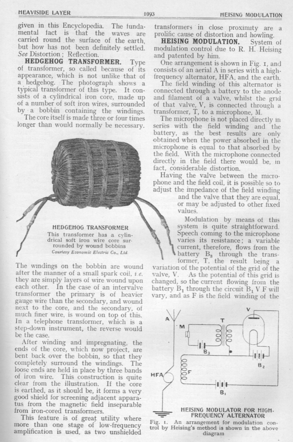
One arrangement is shown in Fig. 1, and
consists of an aerial A in series with a high-
frequency alternator, HFA, and the earth.

The field winding of this alternator is
connected through a battery to the anode
and filament of a valve, whilst the grid
of that valve, V, is connected through a
transformer, T, to a microphone, M.

The microphone is not placed directly in
series with the field winding and the
battery, as the best results are only
obtained when the power absorbed in the
microphone is equal to that absorbed by
the field. With the microphone connected
directly in the field there would be, in
fact, considerable distortion.

Having the valve between the micro-
phone and the field coil, it is possible so to
adjust the impedance of the field winding
and the valve that they are equal,
or may be adjusted to other fixed
values.

Modulation by means of this
system is quite straightforward.
Speech coming to the microphone
varies its resistance; a variable
current, therefore, flows from the
battery B, through the trans-
former, T, the result being a
variation of the potential of the grid of the
valve, V. As the potential of this grid is
changed, so the current flowing from the
battery B, through the circuit B, V F will
vary, and as F is the field winding of the

PE gt)

Ly i
‘eu ef

Bz
: ‘alele—
B,
HEISING MODULATOR FOR HIGH.

ie FREQUENCY ALTERNATOR

Fig. 1. An arrangement for modulation con-
trol by Heising’s method is shown in the above
diagram