Hollywood1
Recognised text
Text below was produced by optical character recognition and may contain errors. Check it against the original.
464 Proceedings of the ILR.E.

for a 0.16-microsecond time constant, and that the
transient will overshoot its final value, but not’ by
a large amount because of rapid damping.

SINGLE AND COUPLED TUNED
CIRCUITS IN CASCADE

_ Loh® has shown that the amplitude response of
tuned coupled circuits may be made much flatter with
little loss in band width by using in cascade a single

x

PHASE 3
IN

w

“4 3 “2 - [) x 2 3 4

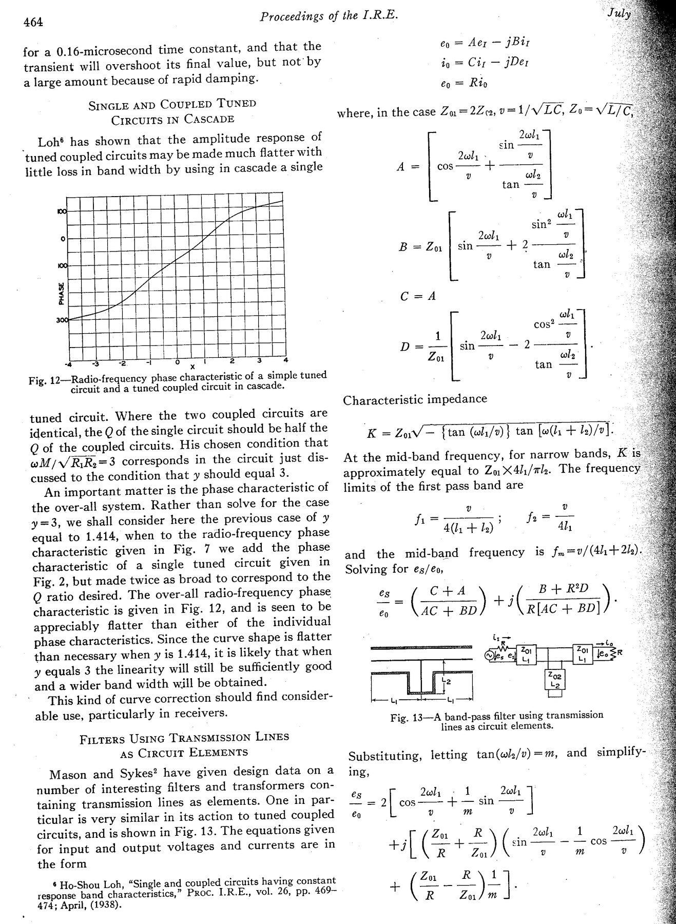
Fig. 12—Radio-frequency phase characteristic of a simple tuned
circuit and a tuned coupled circuit in cascade.

tuned circuit. Where the two coupled circuits are
identical, the Q of the single circuit should be half the
Q of the coupled circuits. His chosen condition that
wM/./Ri:Rz=3 corresponds in the circuit just dis-
cussed to the condition that y should equal 3.

An important matter is the phase characteristic of
the over-all system. Rather than solve for the case
y =3, we shall consider here the previous case of y
equal to 1.414, when to the radio-frequency phase
characteristic given in Fig. 7 we add the phase
characteristic of a single tuned circuit given in
Fig. 2, but made twice as broad to correspond to the
Q ratio desired. The over-all radio-frequency phase
characteristic is given in Fig. 12, and is seen to be
appreciably flatter than either of the individual
phase characteristics. Since the curve shape is flatter
than necessary when y is 1.414, it is likely that when
y equals 3 the linearity will still be sufficiently good
and a wider band width will be obtained.

This kind of curve correction should find consider-
able use, particularly in receivers.

Fitters USING TRANSMISSION LINES
As Crrcuit ELEMENTS

Mason and Sykes? have given design data on a
number of interesting filters and transformers con-
taining transmission lines as elements. One in par-
ticular is very similar in its action to tuned coupled
circuits, and is shown in Fig. 13. The equations given
for input and output voltages and currents are in
the form

6 Ho-Shou Loh, “Single and coupled circuits having constant

response band characteristics,” Proc. I.R.E., vol. 26, pp. 469-
474; April, (1938).

6 = Aer —_ jBir
ip = Ciz — jDex

€g = Rip

where, in the case Zn. =2Z m2, v=1/V LC, Zy= Vie

. Jal,
sin
Joly v
A = {| cos
v wl
tan ——
v
a : why
sin? ——
Zeal, v
B=Z {| sin +
v wl
tan —~
L v
C=A
ni wh
cos oh]
1 Zul, Uv
D=-—-| sin _
Zor v al
a tan ——
vo

Characteristic impedance

K =ZaiV— ftan (wl;/v)} tan foo(dy + l/l:

At the mid-band frequency, for narrow bands, K-i
approximately equal to Zu X4h/ale. The frequency
limits of the first pass band are

v v

A tah)’ Aly

and the mid-band frequency is fm=v/ (44+ 2h)
Solving for es/éo,

es C+A { B+RD
® (set) ates mn)
eo AC + BD R[AC + BD]

Ee |

Fig. 13—A band-pass filter using transmission
lines as circuit elements.

Substituting, letting tan(wle/v) =m, and simplify-
ing, .

és [ uly ~ | . Ql, :
—= cos + — sin |

v m v

TZ. . R wl) 1 wl \
+7 a +=) (sin —— cos
R Zul v m v
(Foz)
R Zor m .