Hollywood2
Recognised text
Text below was produced by optical character recognition and may contain errors. Check it against the original.
» 1939

Narrow band width is obtained when Jz is small; for

this case
m Oz wle/v & Irfola/v = (ale/ 211) .

Let y=R/K, so that R/Zou=2y/m.
Let q = (1/m)[Qols/0) +m — 7]
so that

(wh, /v) = (4 + mq —m).

This substitution will make g=0 correspond to fre-
quency fm, g=1 to fo, and q=—1 to fi. The shape
factor y modifies the shape of the resulting curves
according to the degree of impedance match.

es 1.
aa) —cos (mg—m) > sin (mgm) |

€0

vif (22) { se orm contr}

2y m

i 2
2(5-2)}
m\2y m

By series expansion of the terms, neglecting all terms
with a positive power of m on the assumption that
the band width is small, ;

es . i+ yy?
Sm —r9+5(| | - a).
. &- y

Now introduce the new variable X¥ =qy. Then

—_ 2 2
Sar 4; (- ~*).
€9 y ¥

This is identical to (3) for the tuned coupled cir-
cuit. Therefore the radio- and video-frequency
characteristics and transient response for the tuned
coupled circuit also apply to this type of trans-
mission-line filter. Table I showing equivalent

TABLE I
TABLE OF EQUIVALENT QUANTITIES

(12)

In Tuned-Coupied-
a General Circuit Terminology In Trans:
erminology mission-Line aye
Mutual | Mutual Filter Definition
Coupling | Coupling} Terminology
M m
1 1 ) 2a Mid-band frequency
wo — —s radians per second
VIC v¥iIC 4h, 42s
BW =kwo =2ya M Cc qs Nominal band width
wo —wo —we radians per second
L CM ray
R R R R Terminal resistance
woh i ahR R
y = Shape factor
R RooCM 4hZn K
R R 2woZor
a —_ — Damping factor
2L 2L aR
M Co ls
k —_— —_ —_ Coupling coefficient
L Cu qt
x x x x Frequency parameter
(w —wo) /a@
qd qd q qd Alternative frequency
parameter X /y
Ao 41,421: Wavelength on line
for wo

Hollywood: Single-Sideband Filter Theory

465

quantities will help in making translations from one
system to the other. Guillemin? gives some interest-
ing data on tuned coupled circuits as band-pass
filters which is related to the present subject matter.

It should be noticed that the parameter q is really
more suitable than X, since from the manner in
which it was formulated it expresses “amount applied
frequency differs from resonance” divided by “half
the band width.” Band width BW extends from 4
of —1 tog of 1.

In regard to physical realizability of the trans-.
mission-line structures, the characteristic impedances
required in the elements are quite reasonable for
terminal impedances ranging upward from 300 ohms, ™
and the losses should be small. Further design data ,
will be given later.

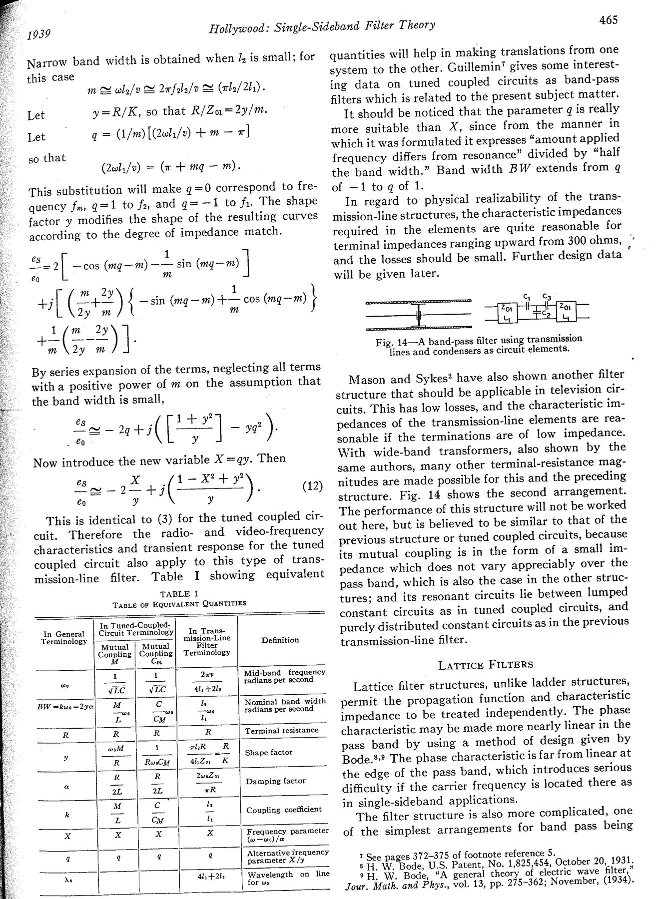
—}— Ket Zos

Fig. 14—A band-pass filter using transmission
lines and condensers as circuit elements.

Mason and Sykes? have also shown another filter
structure that should be applicable in television cir-
cuits. This has low losses, and the characteristic im-
pedances of the transmission-line elements are rea-
sonable if the terminations are of low impedance.
With wide-band transformers, also shown by the
same authors, many other terminal-resistance mag-
nitudes are made possible for this and the preceding
structure. Fig. 14 shows the second arrangement.
The performance of this structure will not be worked
out here, but is believed to be similar to that of the
previous structure or tuned coupled circuits, because
its mutual coupling is in the form of a small im-
pedance which does not vary appreciably over the
pass band, which is also the case in the other struc-
tures; and its resonant circuits lie between lumped
constant circuits as in tuned coupled circuits, and
purely distributed constant circuits as in the previous
transmission-line filter.

Lattice FILTERS

Lattice filter structures, unlike ladder structures,
permit the propagation function and characteristic
impedance to be treated independently. The phase
characteristic may be made more nearly linear in the
pass band by using a method of design given by
Bode.®? The phase characteristic is far from linear at
the edge of the pass band, which introduces serious
difficulty if the carrier frequency is located there as
in single-sideband applications.

The filter structure is also more complicated, one
of the simplest arrangements for band pass being

7 See pages 372-375 of footnote reference 5.

8 H. W. Bode, U.S. Patent, No. 1,825,454, October 20, 1931.

9H. W. Bode, “A general theory of electric wave filter,”
Jour. Math. and Phys., vol. 13, pp- 275-362; November, (1934).