Making the most of your receiver Eddystone Stratton VK7AG 0003
Recognised text
Text below was produced by optical character recognition and may contain errors. Check it against the original.
For general all round reception of the whole range of frequencies covered
by the receiver, an aerial about 60 feet long is recommended. The greater portion
of it should be well out in the clear and as high above the ground as can con-
veniently be arranged. A tree is often available and can well be used, but the
aerial proper must not be allowed to touch the leaves or. branches—an insulator
well out from the
tree will ensure
this (see Fig. 1).
Also. keep the
aerial well away
from metal roofs,
gutters, etc., even
if this means
shortening it to
some extent.
Signal pick-up is
greater when the
aerial is kept away Fig. |. A good general purpose aerial. It should be kept

from anything clear of all obstructions.
likely to act as a

screen and this point is definitely more important than obtaining maximum
length. Good insulation is necessary at the lead-in point.

Excellent results will be obtainable on aerials much shorter than 60 feet, par-
ticularly on the shorter wavelengths. This applies especially on board ship,
where it may be difficult to erect a long aerial.

At the rear of the receiver are two terminals, one marked ‘‘A’’ and the
other ‘‘AE”. The latter is normally strapped to the chassis and should remain
so when a single wire is used. The aerial lead-in wire is attached to terminal
‘“A"” and the earth to terminal ‘‘AE’’. By the way, if you are temporarily stuck
for an aerial, try connecting an earth lead to the aerial terminal ‘‘A’’ (leaving
“AE” blank, of course). It is surprising how good results can be with this system
—often they are better than with a poor indoor aerial.

ol

SPECIAL AERIALS.

Past experience shows that many listeners are particularly interested in
certain shortwave broadcast stations, or possibly in one of the amateur bands,
and wish to obtain optimum results just where their interests lie.

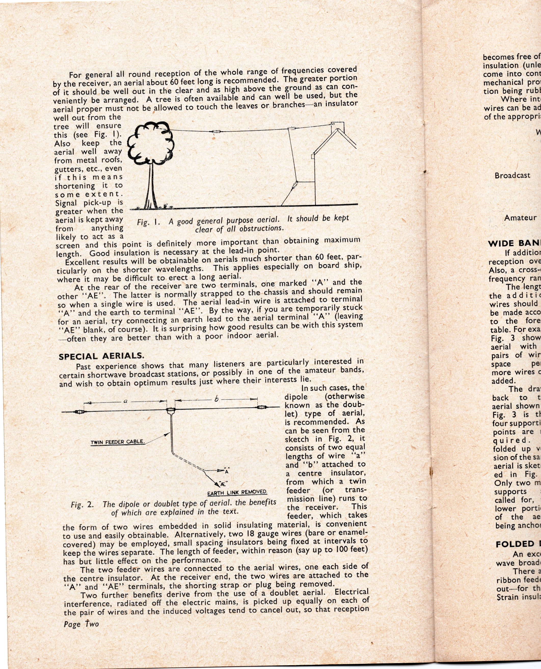
In such cases, the

Oe ee dipole (otherwise

pees eo a _atm—— known as the doub-
let) type of aerial,

is recommended. As

Ly can be seen from the
sketch in Fig. 2, it

\ consists of two equal

698

lengths of wire “‘a

TWIN FEEDER CABLE.

SS g and ‘‘b’’ attached to

axe a centre insulator,

Ca from which a twin

EARTH LINK REMOVED. feeder (or trans-

Fig. 2. The dipole or doublet type of aerial. the benefits Mission line) runs to
of which are explained in the text. the receiver. This

feeder, which takes

the form of two wires embedded in solid insulating material, is convenient _

to use and easily obtainable. Alternatively, two 18 gauge wires (bare or enamel-
covered) may be employed, small spacing insulators being fixed at intervals to
keep the wires separate. The length of feeder, within reason (say up to 100 feet)
has but little effect on the performance. 3

The two feeder wires are connected to the aerial wires, one each side of
the centre insulator. At the receiver end, the two wires are attached to the
“A” and “AE”? terminals, the shorting strap or plug being removed.

Two further benefits derive from the use of a doublet aerial. Electrical
interference, radiated off the electric mains, is picked up equally on each of
the pair of wires and the induced voltages tend to cancel out, so that reception

Page Two

oi dt

.

becomes free of
insulation (unle
come into cont
mechanical pro’
tion being rubl

Where int
wires can be ad
of the appropri:

V

Broadcast

Amateur

WIDE BAN!
If additior
reception ové
Also, a cross-
frequency ran
The lengt
the additi«
wires should
be made acco
to the fore
table. For exa
Fig. 3 show
aerial with
pairs of wir
space pe
more wires ¢
added.

The dra
back to t
aerial shown
Fig. 3 is tt
four supporti
points are |
quired.
folded up vy
sion of the sa
aerial is sket
ed in Fig.
Only two m
supports
called for,
lower porti
of the ae
being ancho:

FOLDED |
An exc

_ wave broad:

There 2
ribbon feeds
out—for th
Strain insuk: