Making the most of your receiver Eddystone Stratton VK7AG 0004
Recognised text
Text below was produced by optical character recognition and may contain errors. Check it against the original.
equencies covered
he greater portion
round as can con-
be used, but the
ches—an insulator

fn nen

- should be kept

‘taining maximum

than 60 feet, par-
ly on board ship,

ked ‘‘A’’ and the
and should remain
ached to terminal
temporarily stuck
linal ‘‘A’’ (leaving
e with this system

arly interested in
1€ amateur bands,
s lie.

In such cases, the
ole (otherwise
own as the doub-
) type of aerial,
recommended. As
1 be seen from the
stch in Fig. 2, it
nsists of two equal
igths of wire ‘‘a”’
i ‘‘b’’ attached to
centre insulator,
mm which a twin
der (or trans-
ssion line) runs to
= receiver. This
-der, which takes
rial, is convenient
ss (bare or enamel-
xed at intervals to
‘say up to 100 feet)

, one each side of
re attached to the
removed.

_ aerial. Electrical
=qually on each of
, So that reception

~

becomes free of local interfering noises. Also, the feeder does not require further
insulation (unless the spaced type is used), and may be allowed to run near, or
come into contact with metal objects. At times it may be wise to add some
mechanical protection such as a wrapping of tape, to prevent the feeder insula-
tion being rubbed away by wind movement.

Where interest lies in a particular frequency band, the lengths of the aerial
wires can be adjusted to give optimum results. The following table gives details
of the appropriate lengths to use for the short wave broadcast and amateur bands.

Wavelength Frequency Lengths of ‘‘a”’
(Metres) (Megacycles) and ‘‘b’’ (feet)
49 6.1 40 ;
(31 9.6 26
{22 11.8 20
Broadcast ' 19 15.1 15.5
\ 16 17.8 13
| 13 21.5 10.5
11 26 9
’ (40 7 33
Amateur 20 14 16.5
(10 28 8.25

WIDE BAND RECEPTION.

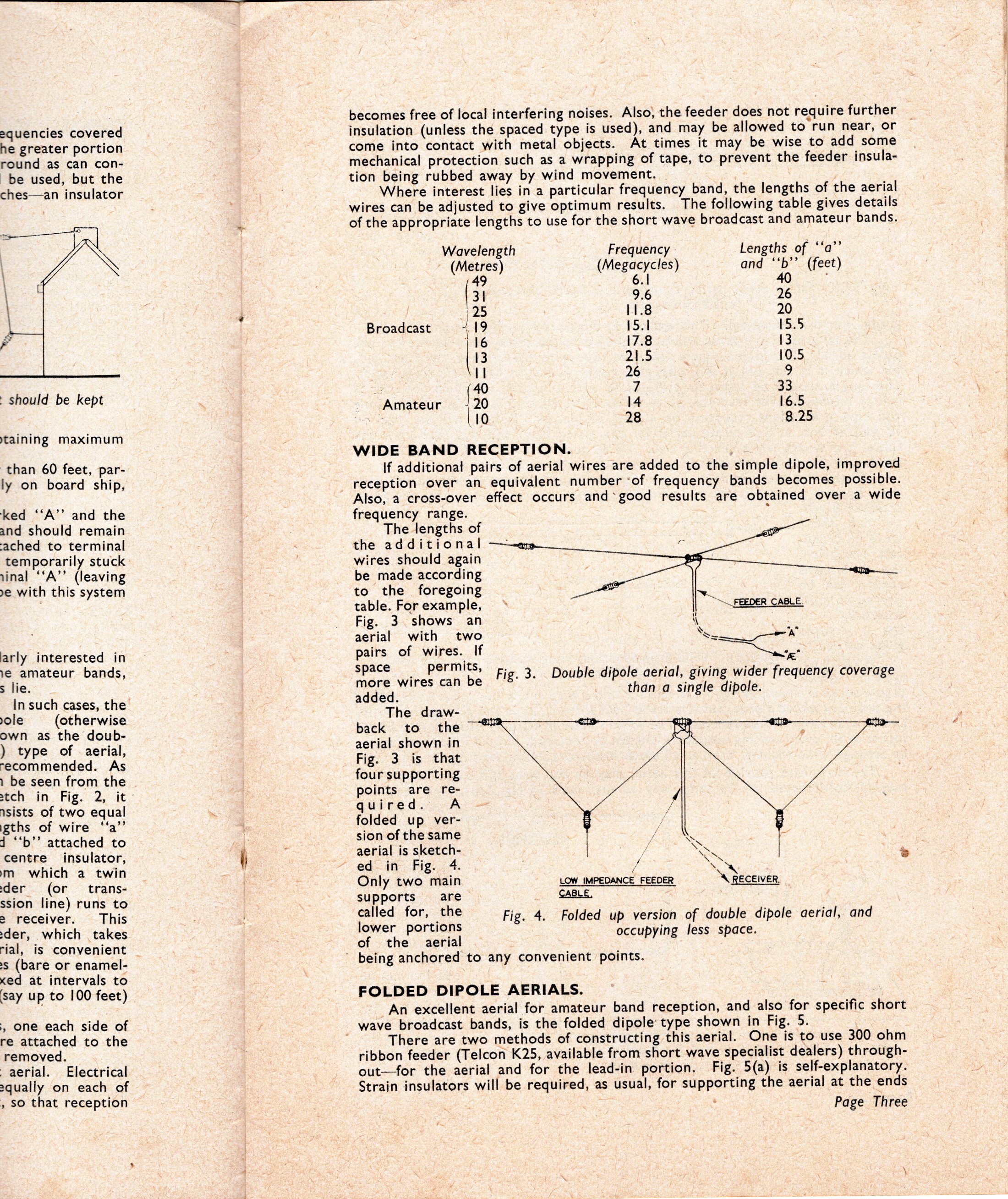
If additional pairs of aerial wires are added to the simple dipole, improved
reception over an_ equivalent number ‘of frequency bands becomes possible.
Also, a cross-over effect occurs and*good results are obtained over a wide
frequency range. .

The lengths of
the additional —wm,
wires should again
be made according
to the foregoing
table. For example,
Fig. 3 shows an \
aerial with two See

pairs of wires. If SOE

pone Chee Fig. 3. Double dipole aerial, giving wider frequency coverage
than a single dipole.
added.
The draw-

back to the
aerial shown in
Fig. 3 is that
four supporting
points are re-
quired. A
folded up ver-
sion of the same
aerial is sketch-

ed in Fig. 4. 7, N

Only two main LOW IMPEDANCE FEEDER A RECEIVER

supports are CABLE,

called for, the Fig. 4. Folded up version of double dipole aerial, and
lower portions occupying less space.

of the aerial

’ being anchored to any convenient points.

FOLDED DIPOLE AERIALS.
An excellent aerial for amateur band reception, and also for specific short

_ wave broadcast bands, is the folded dipole type shown in Fig. 5.

There are two methods of constructing this aerial. One is to use 300 ohm
ribbon feeder (Telcon K25, available from short wave specialist dealers) through-
out—for the aerial and for the lead-in portion. Fig. 5(a) is self-explanatory.
Strain insulators will be required, as usual, for supporting the aerial at the ends

Page Three