Making the most of your receiver Eddystone Stratton VK7AG 0005
Recognised text
Text below was produced by optical character recognition and may contain errors. Check it against the original.
INSULATING SUPPORT. and some addi-
tional mechani-

is ee fi cal support will
LY ay Pan be required at
is the centre.

b 6 The second
method is to
employ 14 -or

H 16 gauge wire,

oe 4 spaced = apart

LIZZ jg- RECEIVER TERMINALS. with small in-

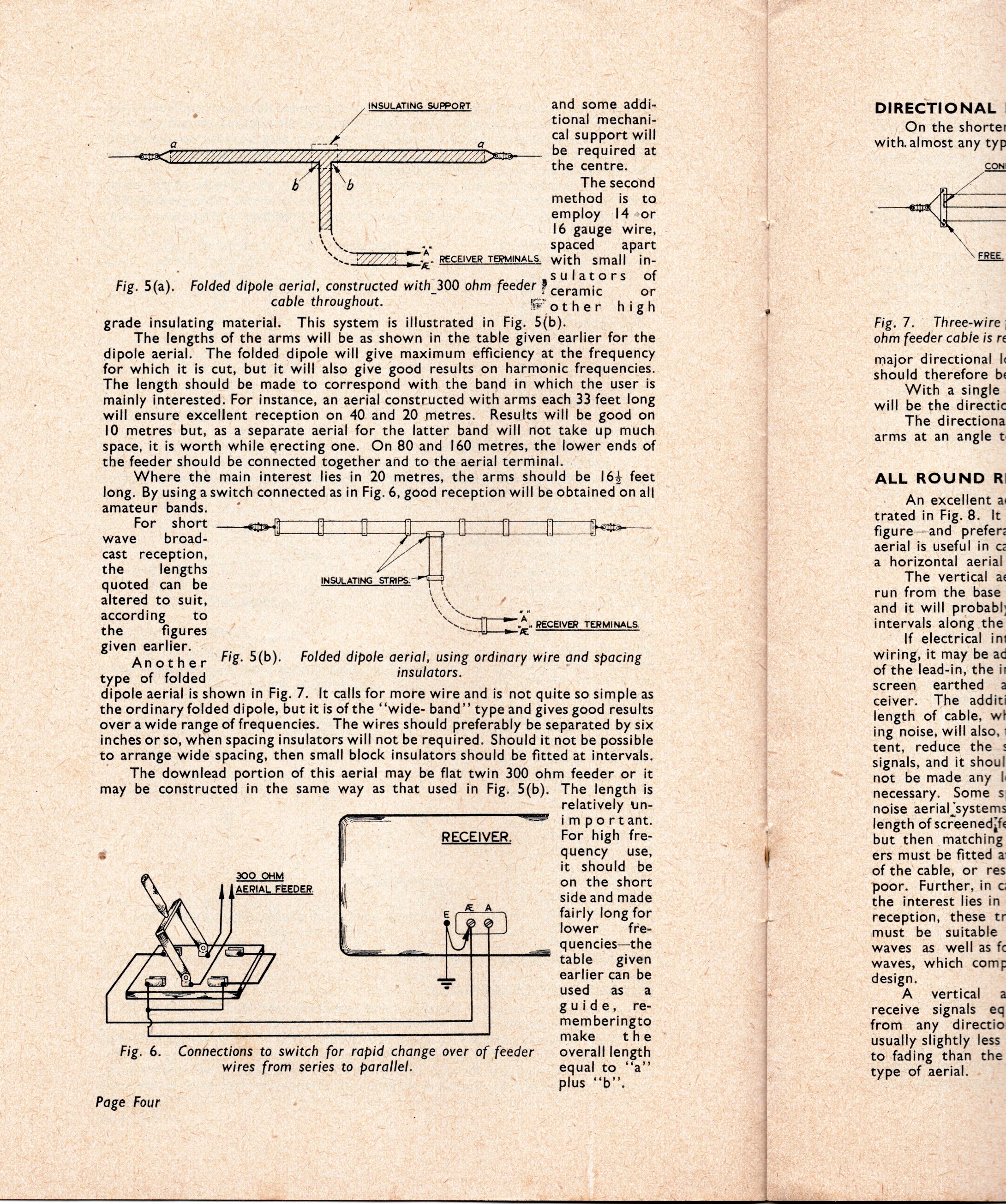
Fig. 5(a). Folded dipole aerial, constructed with_300 ohm feeder penionn oo 2
cable throughout. other high

grade insulating material. This system is illustrated in Fig. 5(b).

The lengths of the arms will be as shown in the table given earlier for the
dipole aerial. The folded dipole will give maximum efficiency at the frequency
for which it is cut, but it will also give good results on harmonic frequencies.
The length should be made to correspond with the band in which the user is
mainly interested. For instance, an aerial constructed with arms each 33 feet long
will ensure excellent reception on 40 and 20 metres. Results will be good on
10 metres but, as a separate aerial for the latter band will not take up much
space, it is worth while erecting one. On 80 and 160 metres, the lower ends of
the feeder should be connected together and to the aerial terminal.

Where the main interest lies in 20 metres, the arms should be 164 feet
long. By using aswitch connected as in Fig. 6, good reception will be obtained on all
amateur bands.

for, short: _sated a a ee
wave __ broad-
cast reception,
the lengths
quoted can be INSULATING STRIPS.

\
altered to suit, eae /
according to soto. on
~ oA. RECE! :
~—_ [Treg RECEIVER TERMINALS

the figures
i lier.

patel Fig. 5(b). Folded dipole aerial, using ordinary wire and spacing

insulators.

Another
type of folded
dipole aerial is shown in Fig. 7. It calls for more wire and is not quite so simple as
the ordinary folded dipole, but it is of the ‘‘wide- band”’ type and gives good results
over a wide range of frequencies. The wires should preferably be separated by six
inches or so, when spacing insulators will not be required. Should it not be possible
to arrange wide spacing, then small block insulators should be fitted at intervals.

The downlead portion of this aerial may be flat twin 300 ohm feeder or it
may be constructed in the same way as that used in Fig. 5(b). The length is

relatively un-

“= important.
RECEIVER. For high fre-
quency use,

it should be

on the short

3 side and made
€ 3 fairly long for
lower fre-
quencies—the
table given
earlier can be
used as a
guide, re-
memberingto

e

300 _ OHM
AERIAL FEEDER.

fH

id make the
Fig. 6. Connections to switch for rapid change over of feeder _ overall length
wires from series to parallel. equal to ‘‘a’”’
plus ‘*b’’.
Page Four

bi ctn deinen stiches

DIRECTIONAL |
On the shorter
with. almost any typ

CON!

Fig. 7. Three-wire
ohm feeder cabie is re

major directional |
should therefore bs
With a single
will be the directic
The directiona
arms at an angle t

ALL ROUND R

An excellent a
trated in Fig. 8. It
figure—and_ prefer:
aerial is useful in cz
a horizontal aerial

The vertical a
run from the base
and it will probabl:
intervals along the

If electrical int
wiring, it may be ac
of the lead-in, the i
screen earthed 2
ceiver. The additi
length of cable, wt
ing noise, will also, :
tent, reduce the
signals, and it shoul
not be made any |
necessary. Some s
noise aerial systems
length of screened;fe
but then matching
ers must be fitted a
of the'cable, or res
poor. Further, in c
the interest lies in
reception, these tr
must be suitable
waves as well as fc
waves, which comf
design.

A vertical a
receive signals eq
from any directio
usually slightly less
to fading than the
type of aerial.