Making the most of your receiver Eddystone Stratton VK7AG 0006
Recognised text
Text below was produced by optical character recognition and may contain errors. Check it against the original.
and some addi-
tional mechani-
cal support will
be required at
the centre.
The second
method is to
employ 14 «or
16 gauge wire,
spaced apart
NALS. with small in-
sulators of

der} ceramic or
other high
g. 5(b).

given earlier for the
icy at the frequency
armonic frequencies.
n which the user is
ms each 33 feet long
ilts will be good on
| not take up much
s, the lower ends of
rminal.

should be 164 feet
ill be obtained on all

eee

“-~ RECEIVER TERMINALS.

A
y wire and spacing

ot quite so simple as
id gives good results
be separated by six
ild it not be possible
e fitted at intervals.
0 ohm feeder or it
9(b). The length is
relatively un-
“=== important.
For high fre-
quency use,
it should be
on the short
side and made
fairly long for
lower fre-
quencies—the
table given
earlier can be
used as a
guide, re-
memberingto
make the
er overall length
equal to ‘‘a”’
plus ‘‘b’’,

DIRECTIONAL EFFECTS.
On the shorter wavelengths, directional effects are likely to be experienced
with. almost any type of aerial. Advantage can be taken of the effects when recep-
tion from a

CONNECTED TOGETHER. i
particular

is country or sta-
tion is the aim.
i A long wire

aerial will re-
ceive best in
four major dir-
“" ections at acute
op RECENER TERMINALS. angles to the

th
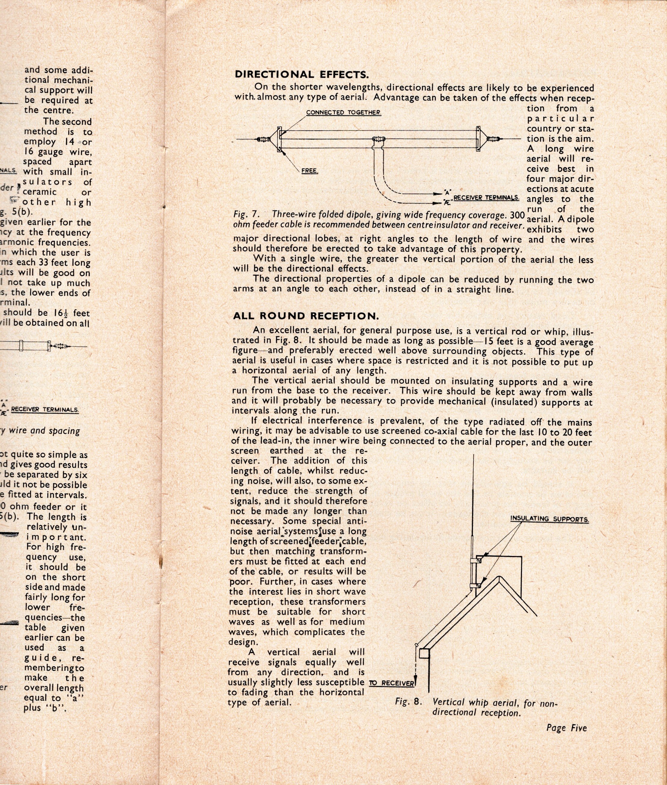
Fig. 7. Three-wire folded dipole, giving wide frequency coverage. 300 lula Bateele
ohm feeder cable is recommended between centreinsulator and receiver. exhibits two

major directional lobes, at right angles to the length of wire and the wires
should therefore be erected to take advantage of this property.

With a single wire, the greater the vertical portion of the aerial the less
will be the directional effects.

The directional properties of a dipole can be reduced by running the two
arms at an angle to each other, instead of in a straight line.

ALL ROUND RECEPTION.

An excellent aerial, for general purpose use, is a vertical rod or whip, illus-
trated in Fig. 8. It should be made as long as possible—I5 feet is a good average
figure—and preferably erected well above surrounding objects. This type of
aerial is useful in cases where space is restricted and it is not possible to put up
a horizontal aerial of any length.

The vertical aerial should be mounted on insulating supports and a wire
run from the base to the receiver. This wire should be kept away from walls
and it will probably be necessary to provide mechanical (insulated) supports at
intervals along the run.

If electrical interference is prevalent, of the type radiated off the mains
wiring, it may be advisable to use screened co-axial cable for the last 10 to 20 feet
of the lead-in, the inner wire being connected to the aerial proper, and the outer
screen earthed at the re- :
ceiver. The addition of this
length of cable, whilst reduc-
ing noise, will also, to some ex-
tent, reduce the strength of
signals, and it should therefore .
not be made any longer than
necessary. Some special anti-
noise aerial ‘systems{use a long
length of screenedjfeederjcable,
but then matching transform-
ers must be fitted at each end
of the cable, or results will be
poor. Further, in cases where
the interest lies in short wave
reception, these transformers
must be suitable for short
waves as well as for medium
waves, which complicates the
design.

A vertical aerial will
receive signals equally well '
from any direction, and is |
usually slightly less susceptible to receiver!
to fading than the horizontal
type of aerial. Fig. 8. Vertical whip aerial, for non-

directional reception.

Page Five