Muscio3
Recognised text
Text below was produced by optical character recognition and may contain errors. Check it against the original.
164 AUSTRALIAN RADIO — THE TECHNICAL STORY

FDM/FM bearer systems were adopted world-wide in preference to
TDM systems using digital radio. Only now, after 25 years, has TDM
come into its own as part of the digital revolution and with it is
coming the rebirth of digital radio.

The difficulty with a multi-channel FM bearer is that to avoid
crosstalk between the channels, a very high order of linearity is
required. Pioneering work in the US and UK during the late 1940s
and early 1950s showed that these problems could be solved
successfully. Indeed they were solved so effectively that by the 1970s
systems carrying as many as 2700 channels were becoming quite
commonplace.

As described in later paragraphs of this chapter, quite a number of
Australian radio engineers participated in the design and
manufacture of wide band FM bearer equipment. At this stage,
however, some features of frequency division multiplexing
equipment are discussed below.

7.3. Open-Wire Carrier Telephony

With the exception of some single wire circuits with earth return used
for telegraphy and to a lesser extent for telephony, practically all
early communication services between isolated areas depended upon
one or more pairs of pole-mounted wires. In these circumstances it is
not surprising to find that the first attempts to obtain some form of
multi-channel operation were concerned with making more efficient
use of the lines already available.

As a means of achieving this end, the International Western
Electric Company (IWE) in the US developed a three-channel carrier
telephone system for use on open-wire lines. In terms of the
availability of suitable types of valves, components and critical
materials, this was a bold venture at the time at which it was
undertaken, By the mid-1920s, a limited number of systems were in
operation in the US and Brazil. Using equipment manufactured
largely in the US, the first three-channel system was placed in service
on the Sydney-Melbourne route in 1925. Further installations of
equipment of overseas origin were made progressively during
succeeding years until by 1942 partial local manufacture was being
undertaken in Australia. However, with the continuing loss of
materials sent by sea during the war, local manufacture of additional
items became an urgent matter and by 1945 such equipments were
being made entirely in Australia by STC.

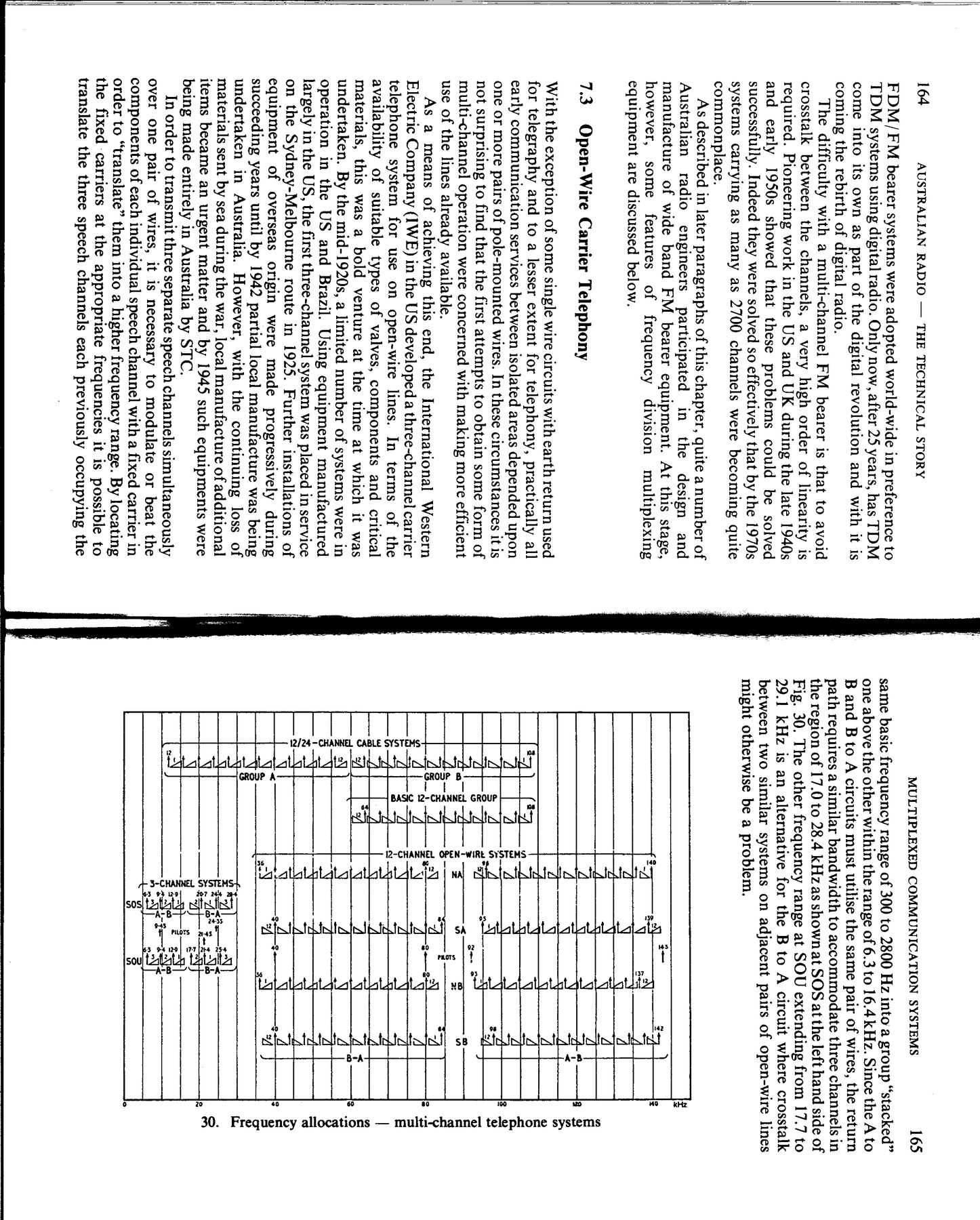
In order to transmit three separate speech channels simultaneously
over one pair of wires, it is necessary to modulate or beat the
components of each individual speech channel with a fixed carrier in
order to “translate” them into a higher frequency range. By locating
the fixed carriers at the appropriate frequencies it is possible to
translate the three speech channels each previously occupying the

MULTIPLEXED COMMUNICATION SYSTEMS 165

same basic frequency range of 300 to 2800 Hz intoa group “stacked”
one above the other within the range of 6.3 to 16.4 kHz. Since the A to
B and B to A circuits must utilise the same pair of wires, the return
path requires a similar bandwidth to accommodate three channels in
the region of 17.0 to 28.4 kHzas shownat SOS at the left hand side of
Fig. 30. The other frequency range at SOU extending from 17.7 to
29.1 kHz is an alternative for the B to A circuit where crosstalk
between two similar systems on adjacent pairs of open-wire lines
might otherwise be a problem.

g
i g-, ) >
‘74 a :
— =
f A q “d
A at
= 5 q JS a
A q a Aa &
= ya 42 2
a, ee a Ea
=F TN = a
JA A q 4 2
Z —
a> 5 a 2 s 3 Y J Z
Al [4 fy UN 2
Als 4 8.4 NS ty 2
aT § = * ee BS , 2
fae at—ti-g , a a
As 2-4 _# ot a < =
Az 8 7 aN Ao. ON A 2
eg 4| e424 4A JA 3
ee ee eee ee ee E
—& a oN a oa 4
gal Ta iy ey ,
Sy} ly Y A q Az 46
z A a r=
= a ee 8
Y rm a mm a i)
| Sy yA) >
7 7 4... N of e 2
< bee + hare ~
As av d aN 4 3 3.
38 2
xq] <= fy
% Fl, 3) :
q Beet 3o2Ne z
— aig} imiay ®
a Z aj g _
= aN 2 ge.
aad s ct a ic
——= 5 Nee
eeay sNT
Vw 2
& 3%