The electrician 2
Recognised text
Text below was produced by optical character recognition and may contain errors. Check it against the original.
THE ELECTRICIAN, OCTOBER 23, 1914. 71

js effected as follows: The radiator circuit is
he inductance K to the wave-length it is desired
of:-the coupling condenser Hi having been first
ircuit BE, F, H, G, J is approximately tuned to the
equency. The circuit D, F, I, G, J is tuned as
esonance with the frequency of the current sup-
Hisitisseen that the inductance of the transformer

therefore its leakage factor, plays an important
ustment of the system. In action the aerial is
the spiral choke I until discharge takes place,
act.that the charging current at a frequency of 350
harge the condenser H, which may he considered
© this current by the inductance I. Therefore,
considered as entirely earthed with regard to the
until the instant of the maximum charge of the con-
.G, A discharge takes place across the gap E, the

500 600 200 800
A-Metres.

.§.— RADIATOR CIRCUIT SIMPLICITHR ENERGISED BY
SPaRK-cor.

which is about lem. The rate at which the discharge
gap occurs is determined by the time constant of
3 E, F, H, G, J, the value of the inductance J -being
make this below that of the radiator circuit. The effect
initial rush of current across the gap E is that the condenser
mes charged and the energy poured into it is set free in the
» which oscillates at its own natural frequency only, of which
ompanying resonance curve (Fig. 3) for this aerial oscillation
The remainder of the charge in the two condensers
n oscillation in the low- frequency circuit D, F, I, G, J.
his energy that isthe remainder of the charge in the two con-
ds utilised at the next charge of the condensers, and owing to
odicity of this circuit agreeing with the periodicity of the
of current and the easier path through the transformer
vided than across the gap, and thus no return flow across the

en: Cee Se Ge i =a

iat ! 4 ay iL ti

100 200 300 400 500 600

ndeavours have been made to produce an oscillatory discharge
oss: the gap, This can only be done by introducing an extra
tance between D and EH, so as to throw this cirenit out of tune.
hotograph (Fig. 1) is considered to be conclusive proof that the
arge under normal conditions is unidirectional, because it is
olutely a single impulse per period of current flowing in the
ary circuit. ksd
»4, curve I., shows the exciting circuit exactly as above, but
spark-coil excitation—that is to say, with resonance of the
2 circuit destroyed and with purely oscillatory current flowing
is circuit.

Fig. 4, curve IT., shows curves of the radiator cirewit under these
conditions, the double hump being very evident.

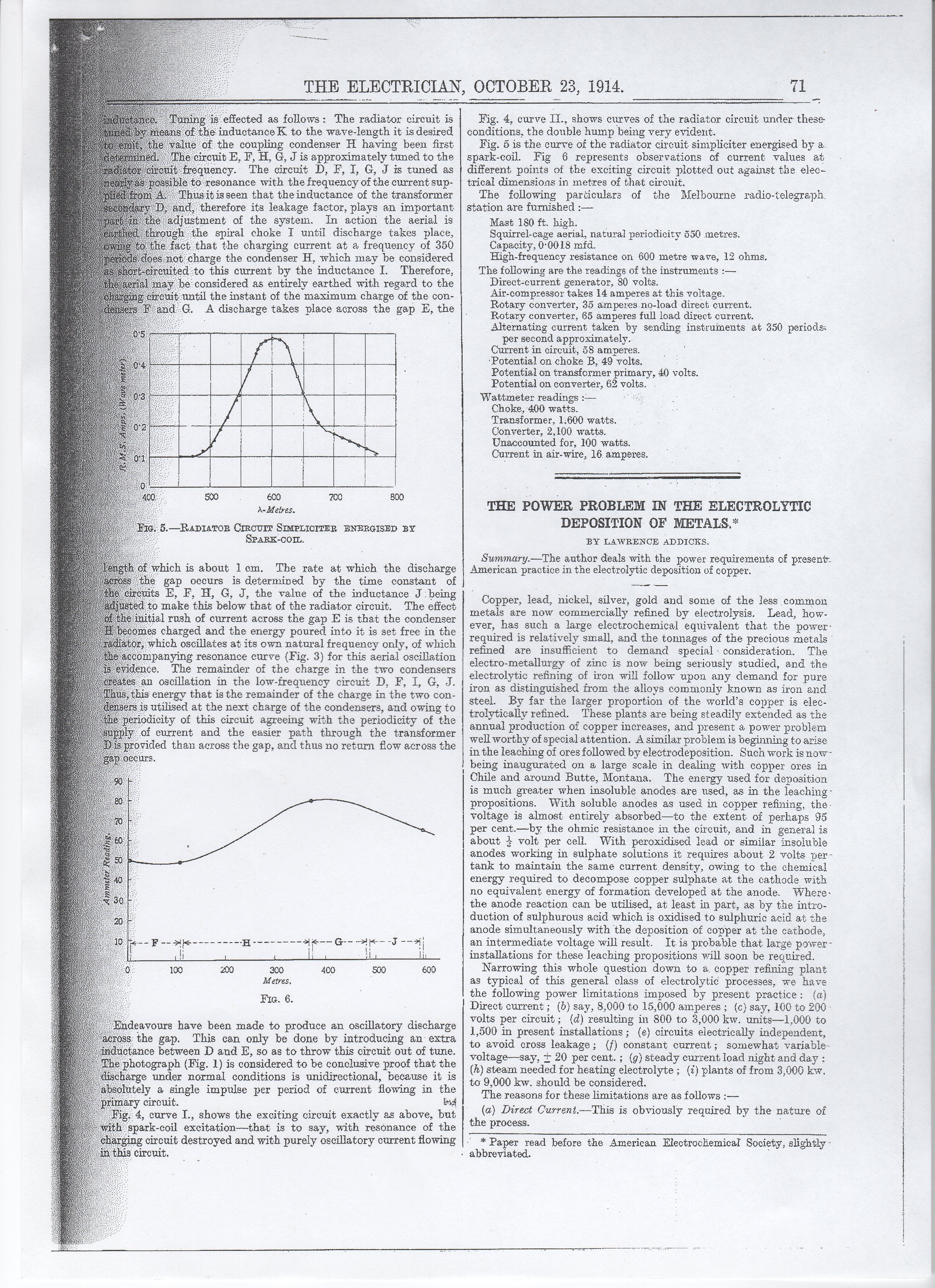
Fig. 5 is the curve of the radiator circuit sinypliciter energised by a
spark-coil. Fig 6 represents observations of current values at
different points of the exciting circuit plotted out against the elec-
trical dimensions in metres of that circuit.

The following particulars of the Melbourne radio-telegraph
station are furnished :—

Mast 180 ft. high.
Squirrel-cage aerial, natural periodicity 550 metres.
Capacity, 00018 mfd.
High-frequency resistance on 600 metre wave, 12 ohms.
The following are the readings of the instruments :-—
Direct-current generator, 80 volts.
Air-compressor takes 14 amperes at this voltage.
Rotary converter, 35 amperes.no-load direct current.
Rotary converter, 65 amperes full load cirect current.
Alternating current taken by sending instruments at 350 periods:
per second approximately.
Current in circuit, 58 amperes.
‘Potential on choke B, 49 volts.
Potential on transformer primary, 40 volts.
Potential on converter, 62 volts.
Wattmeter readings :— :
Choke, 400 watts.
Transformer, 1.600 watts.
Converter, 2,100 watts.
Unaccounted for, 100 watis.
Current in air-wire, 16. amperes.

THE POWER PROBLEM IN THE ELECTROLYTIC
DEPOSITION OF METALS,*
BY LAWRENCE ADDICKS.

Summary.—The author deals with the power requirements of present.
American. practice in the electrolytic deposition of copper.

Copper, lead, nickel, silver, gold and some of the less common
metals are now commercially refined by electrolysis. Lead, how-
ever, has such a large electrochemical equivalent that the power-
required is relatively small, and the tonnages of the precious metals
refined are insufficient to demand special - consideration. The
electro-metallurgy of zinc is now being seriously studied, and the
electrolytic refining of iron will follow upon any demand for pure
iron as distinguished from the alloys commonly known as iren and
steel. By far the larger proportion of the world’s copper is elec-
trolytically refined. These plants are being steadily extended as the
annual production of copper increases, and present a power problem
well worthy of special attention. A similar problem is beginning to arise
in the leaching of ores followed by electrodeposition. Such work is now
being inaugurated on a large scale in dealing with copper ores in
Chile and around Butte, Montana. The energy used for deposition
is much greater when insoluble anodes are used, as in the leaching -
propositions. With soluble anodes as used in copper refining, the
voltage is almost entirely absorbed—to the extent of perhaps 95
per cent.—by the ohmic resistance in the circuit, and in general is
about 3 volt per cell. With peroxidised lead or similar imsoluble
anodes “working in sulphate solutions it requires about 2 volts per-
tank to maintain the same current density, owing to the chemical
energy required to decompose copper sulphate at the cathode with
no equivalent energy of formation developed at the anode. Where-
the anode reaction can be utilised, at least in part, as by the intro-
duction of sulphurous acid which is oxidised to sulphuric acid at the
anode simultaneously with the deposition of copper at the cathode,
an intermediate voltage will result. It is probable that large power -
installations for these leaching propositions will soon be required.

Narrowing this whole question down to a. copper refining plant
as typical of this general class of electrolytic processes, we have
the following power limitations imposed by present practice: {a}
Direct current ; (6) say, 8,000 to 15,000 amperes ; (c) say, 100 to 200-
volts per circuit; (d) resulting in 800 to 3,000 kw. units—1,000 to
1,500 in present installations; (e) circuits electrically independent,
to avoid cross leakage; (f) constant current; somewhat variable-
voltage—say, + 20 per cent. ; (g) steady current Ioad night and day :
(2) steam needed for heating electrolyte ; (7) plants of from 3,006 lew.
to 9,000 kw. should be considered.

The reasons for these limitations are as follows :—

(a) Direct Current.—This is obviously required by the nature of
the process.

* Paper read before the American Electrochemical Society, slightly -

» abbreviated.